Reflection structure

A reflective structure and reflector technology, which is applied in reflectors, lighting and heating equipment, transportation and packaging, etc., can solve the problems of light field loss of light-emitting panels, and achieve the effect of avoiding light loss and light dispersion

Active Publication Date: 2022-04-12
AU OPTRONICS CORP
View PDF6 Cites 0 Cited by
  • Summary
  • Abstract
  • Description
  • Claims
  • Application Information

AI Technical Summary

Problems solved by technology

[0002] Depending on the application of different occasions and states, the light-emitting panel will require a specific light field distribution. For example, the light-emitting panel used in a car must focus the light field of the light-emitting panel on the left and right sides of the light-emitting panel in response to the specific angle of the driver's seat and passenger seat. Both sides to increase the visibility of users in the driver's seat and passenger seat. However, the luminous panels used in vehicles often have the problem of light field loss on the side facing the front windshield of the vehicle and the opposite lower side

Method used


Image

  • Reflection structure
  • Reflection structure
  • Reflection structure

Examples


Embodiment Construction

[0034] The present invention will be described in detail below in conjunction with the accompanying drawings and specific embodiments, but not as a limitation of the present invention.

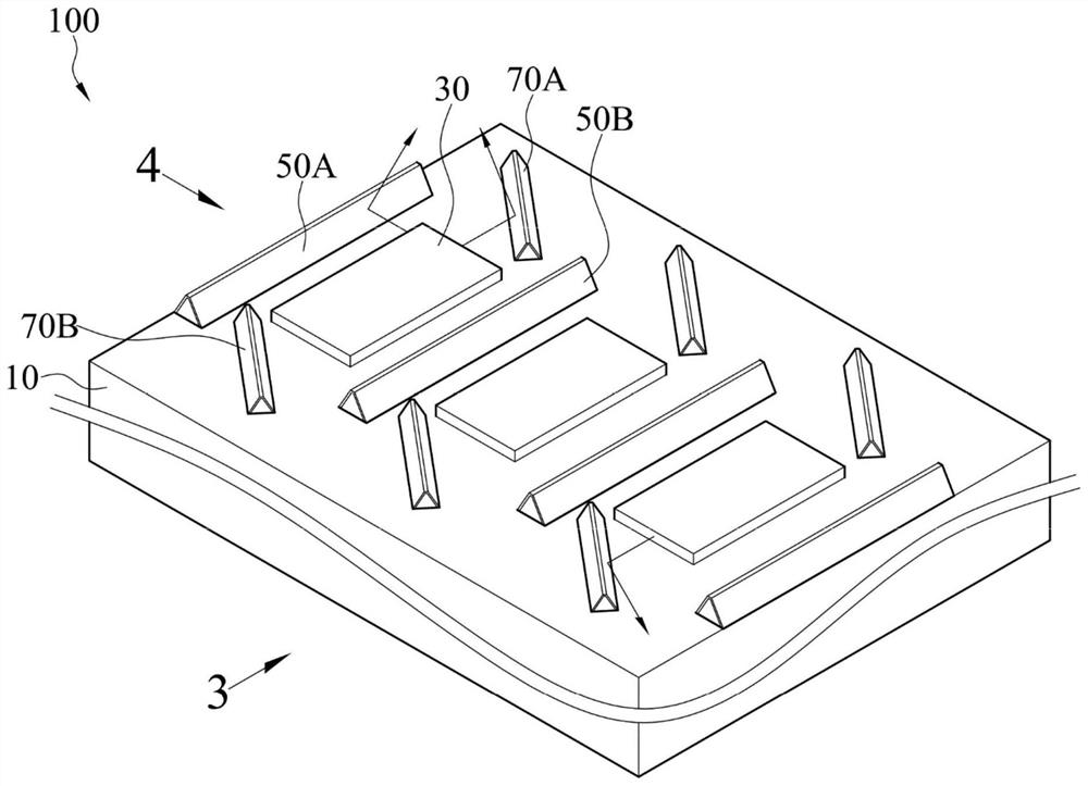
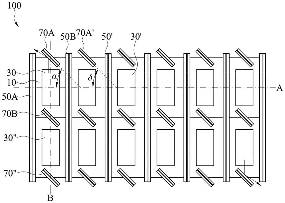
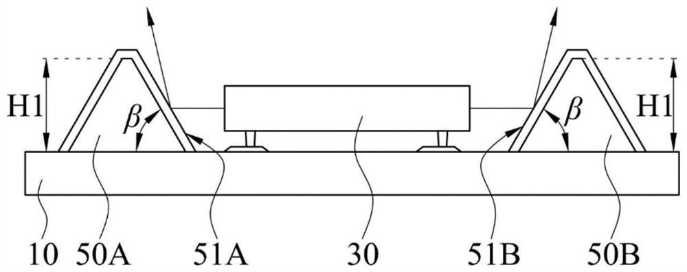
[0035] see figure 1 and figure 2 . figure 1 It is a three-dimensional schematic diagram of a reflective structure according to a first embodiment. figure 2 It is a top view of the reflective structure according to a first embodiment. The reflective structure 100 includes a substrate 10 , a light emitting element 30 , two first reflectors 50A, 50B and two second reflectors 70A, 70B. The reflective structure 100 can be applied to a light-emitting panel, such as a light-emitting panel of a car screen.

[0036] The light emitting element 30 is disposed on the substrate 10 , and a virtual reference axis A is parallel to the substrate 10 and passes through the center of the light emitting element 30 . In the first embodiment, the light emitting element 30 is, for example, an LED or a micro-LE...


PUM

PropertyMeasurementUnit
Angleaaaaaaaaaa

Abstract

The invention discloses a reflecting structure which comprises a substrate, a light-emitting element, two first reflectors and two second reflectors. The light-emitting element is disposed on the substrate, and the virtual reference axis is parallel to the substrate and passes through the center of the light-emitting element. The two first reflectors are arranged on the two opposite sides of the light-emitting element respectively and are perpendicular to the reference axis. The two second reflectors are arranged on the other two opposite sides of the light-emitting element respectively, and the included angle between the axis, extending in the long edge direction, of the two second reflectors and the reference axis ranges from 15 degrees to 75 degrees.

Description

technical field [0001] The invention relates to a reflective structure, in particular to a reflective structure of a luminescent panel. Background technique [0002] Depending on the application of different occasions and states, the light-emitting panel will require a specific light field distribution. For example, the light-emitting panel used in a car must focus the light field of the light-emitting panel on the left and right sides of the light-emitting panel in response to the specific angle of the driver's seat and passenger seat. The two sides are used to increase the visibility of users in the driver's seat and the passenger's seat. However, the light-emitting panels for vehicles often have the problem of light field loss on the side facing the front windshield of the vehicle and the opposite lower side. Contents of the invention [0003] In view of this, a reflective structure is provided, including a substrate, a light emitting element, two first reflectors and t...

Claims


Application Information

Patent Timeline
IPC IPC(8): F21V7/00F21V7/10F21Y115/10F21W106/00
Inventor 李佳安林冠亨陈奕宏
Owner AU OPTRONICS CORP
Why Eureka
Try Eureka