High speed data bus driver

A data bus, bus technology, applied in the direction of electrical digital data processing, instruments, etc., can solve the problem that the form of the bus driver does not meet the needs of the application

Inactive Publication Date: 2004-03-24
THOMSON LICENSING SA
View PDF1 Cites 0 Cited by
  • Summary
  • Abstract
  • Description
  • Claims
  • Application Information

AI Technical Summary

Problems solved by technology

[0005] The present invention is due in part to the recognition that while relative simplicity and the existence of a large number of compatible devices make 2

Method used


Image

  • High speed data bus driver
  • High speed data bus driver
  • High speed data bus driver

Examples


Embodiment Construction

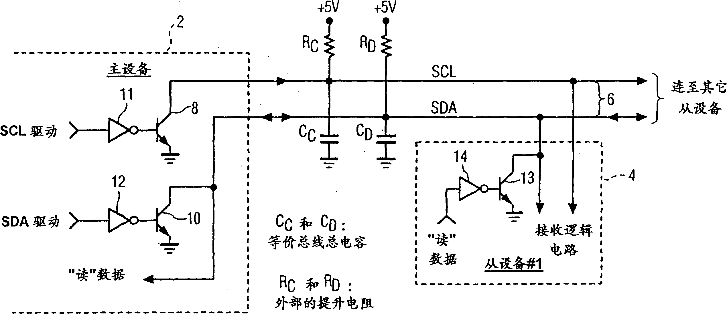
[0025] in such as figure 1 shown as I 2 In the traditional bus system of the C bus, the master device 2 passes through the I 2 C bus 6 is connected to slave device 4 (labeled as slave device #1). According to I 2 C bus rules, the labels SDA and SCL are used to identify the serial data line and the clock line respectively. The master device 2 has a driver respectively to drive each line. more specifically, figure 1 The middle lines SCL and SDA are respectively driven by NPN bipolar transistors 8 and 10 connected thereto.

[0026]The base of each transistor 8 and 10 is connected to the output of an inverter 11, 12 respectively. The independent drive signals SCL drive and SDA drive are respectively connected to the input terminals of the corresponding inverters 11 and 12 . When the SCL drive and SDA drive signals are logic high, the respective NPN transistors 8 and 10 are not turned on, and the lines SCL and SDA are raised to a high level through the boost resistors RC and...


PUM


Abstract

Information is coupled to a data bus such as an I2C data bus using a push-pull circuit. The push-pull circuit provides for communicating on the data bus at two different data rates. The push-pull circuit includes an active pull-up device that is enabled during a first push-pull mode of operation for providing a high data rate. During a second normal mode of operation, the active pull-up device is disabled providing a low data rate. When the active pull-up device is deactivated, the clock and data buses are driven by the external resistors connected thereto at a data rate lower than the data rate during the first mode.

Description

technical field [0001] The present invention relates to digital data bus systems. Background technique [0002] Some systems, such as consumer electronics systems, typically include multiple devices, such as integrated circuits, connected together by a data bus to transfer information between each other. An example of this type of system is a television receiver, which includes an I 2 C serial data bus that transfers information between the controlling microprocessor and the tuner, enabling the tuner to tune a channel. I 2 C is known as a serial data bus and includes two data lines, a clock line labeled SCL, and a serial data line called SDA that transfers information between devices connected to the bus. Each device has a unique address, ensuring that information on the bus can be sent directly to a specific device. Each device can send information, can receive information, or both send and receive according to the needs of the device function. In addition to sending a...

Claims


Application Information

Patent Timeline
IPC IPC(8): G06F13/42
Inventor J・图尔茨W・J・特斯丁
Owner THOMSON LICENSING SA
Why Eureka
Try Eureka