Simulation calibration device and motor vehicle exhaust remote sensing monitoring equipment

A technology for simulating calibration and air intake holes, which is applied in measuring devices, color/spectral characteristic measurement, material analysis through optical means, etc. It can solve problems such as the inability to judge whether the exhaust gas information is correct, and the exhaust gas monitoring time is short.

Pending Publication Date: 2022-04-12
ANHUI QINGYU PHOTOELECTRIC TECH
View PDF0 Cites 0 Cited by
  • Summary
  • Abstract
  • Description
  • Claims
  • Application Information

AI Technical Summary

Problems solved by technology

However, the driving speed of the vehicle is high, so that the exhaust gas left by the vehicle passes through the monitoring optical path quickly, and the monitoring equipment takes a short time to monitor the exhaust gas, so it is impossible to judge whether the exhaust gas information collected by the monitoring equipment in a short time is correct.

Method used


Image

  • Simulation calibration device and motor vehicle exhaust remote sensing monitoring equipment
  • Simulation calibration device and motor vehicle exhaust remote sensing monitoring equipment
  • Simulation calibration device and motor vehicle exhaust remote sensing monitoring equipment

Examples


Embodiment 2

[0041] The second embodiment discloses the structure of the one-way ratchet assembly on the basis of the first embodiment, that is, the slide bar 17 is provided with a plurality of mounting grooves 171 for placing the one-way ratchet assembly, and the one-way ratchet assembly includes a rotating roller 31 The one-way pawl 30 that is rotatably connected to the inner wall of the installation groove 171, the one-way pawl 30 extends out of the installation groove 171 and is in contact with the ratchet 19, and the one-way pawl 30 is attached to the inner wall of one end of the installation groove 171, the one-way The ratchet 30 leans against the inner wall of one end of the installation groove 171, so that the one-way ratchet 30 can only deflect to the other end of the installation groove 171, that is, the one-way ratchet 30 can only deflect in one direction. Slot 171, the one-way ratchet 30 is attached to the left end of the installation groove 171, the upper rotating column 18 is ...

Embodiment 3

[0043] Embodiment three optimizes the push pedal 2 on the basis of embodiment one, that is: the circuit formed by the wire 12 connected in series with the power supply 13, the electromagnet 14 and the trigger switch is not set on the fixed push pedal 2, and the fixed push pedal 2 2 The inner end surface is inlaid with iron blocks. When the electromagnet 14 on the push plate 2 at the left end is energized, the electromagnet 14 attracts the iron block on the push plate 2 at the right end, so that the push plate 2 at the left end slides to the right, and the push plate 2 at the left end When the electromagnet 14 on the push plate 2 is powered off, the electromagnet 14 loses its magnetism, so that the push plate 2 at the left end slides to the left under the elastic action of the elastic connecting rod 3 to reset, and by canceling the circuit in the push plate 2 at the right end, the The manufacturing cost and production difficulty of push plate 2.

[0044] A motor vehicle exhaust...


PUM


Abstract

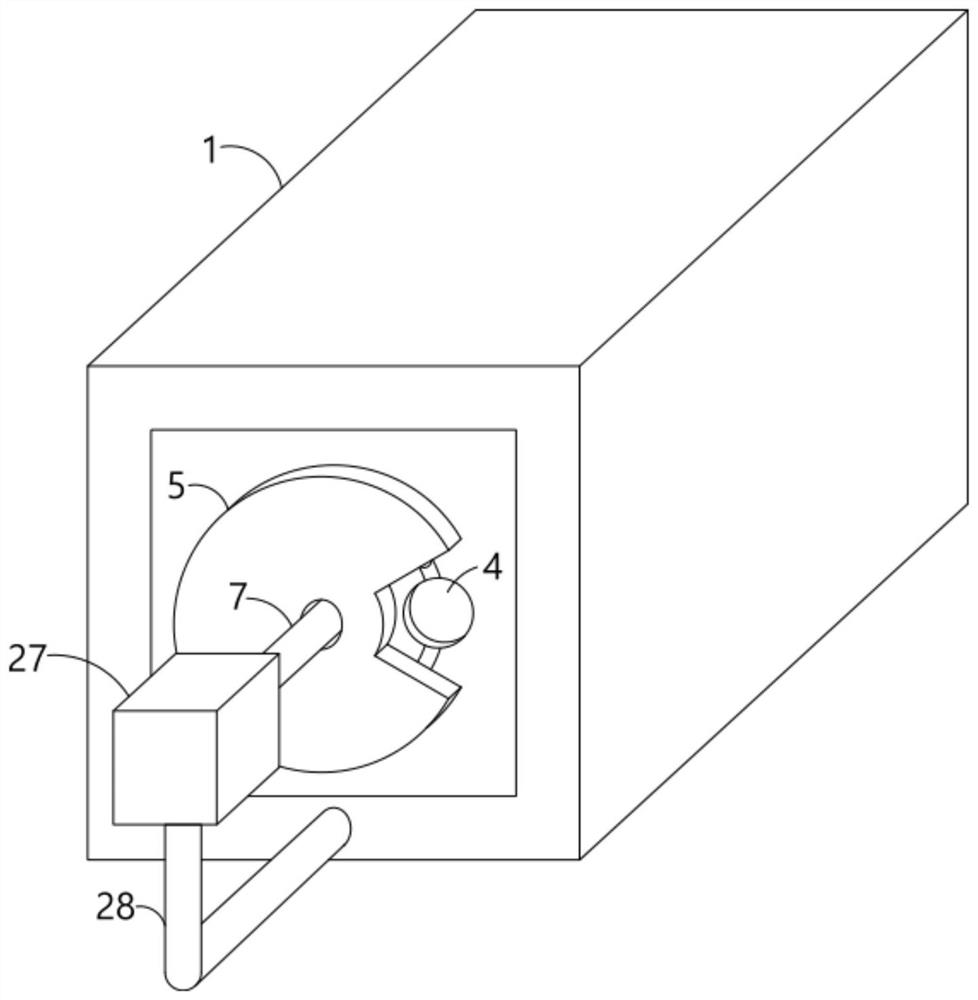
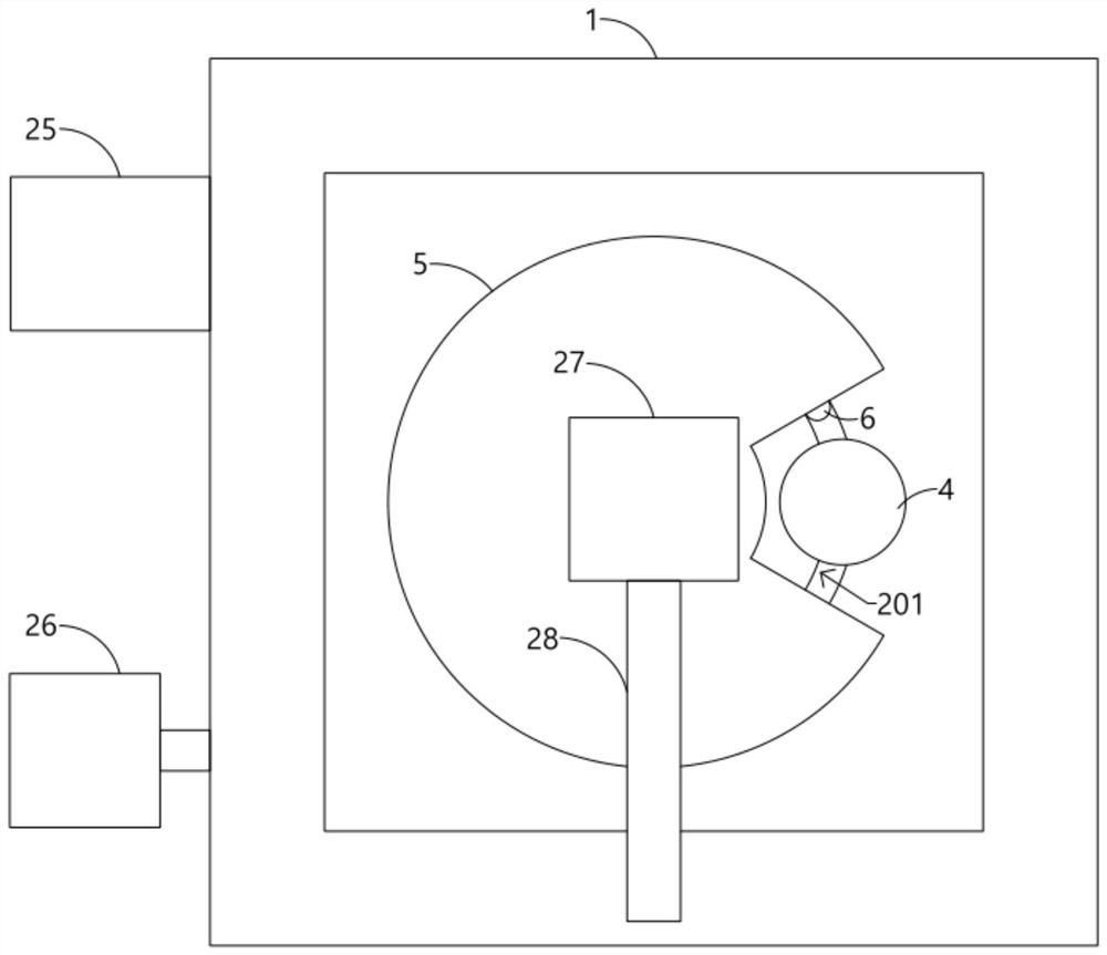
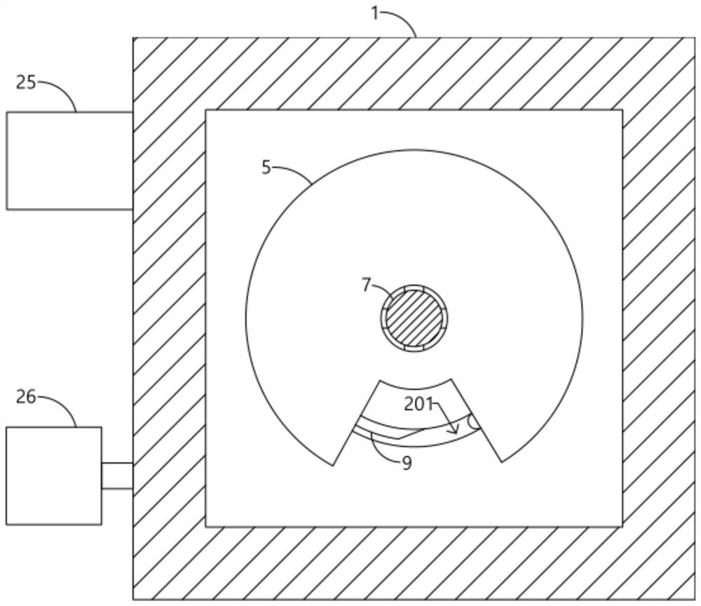
The simulation calibration device comprises a simulation cylinder, push plates with light-transmitting glass are arranged at the two ends of the simulation cylinder, notch rotating discs are arranged on the outer end faces of the push plates, and a circuit formed by a power source, an electromagnet and a trigger switch which are connected in series through a wire is arranged in each push plate. The device comprises a simulation cylinder, the simulation cylinder is fixedly connected with a notch turntable, a push plate which is arranged in a sliding manner is fixedly connected with two sliding rods, a plurality of one-way pawl assemblies are arranged on the sliding rods at intervals, the inner wall of the simulation cylinder is connected with an exhaust hole and an air inlet hole, rotating columns are fixedly connected with ratchets, and the rotating columns are fixedly connected with baffles. The time for the tail gas exhausted by the vehicle to pass through a monitoring light path is simulated, the tail gas diffusion process is simulated and new tail gas for simulation is supplemented in time through cooperative arrangement of a one-way pawl assembly, a rotating column, a baffle, a tail gas conveying box and a tail gas diffusion barrel, and the effect of simulating tail gas emission for multiple times is achieved.

Description

technical field [0001] The invention relates to the technical field of exhaust gas monitoring, in particular to an analog calibration device and remote sensing monitoring equipment for motor vehicle exhaust. Background technique [0002] In the actual monitoring of the road, it is not simply to directly monitor the gas. The vehicle will first pass through the monitoring optical path. At this time, the vehicle body blocks the monitoring optical path. After the entire body passes, the monitoring equipment can form a complete monitoring optical path and leave behind The composition of the exhaust gas is monitored. However, the driving speed of the vehicle is high, so that the exhaust gas left by the vehicle passes through the monitoring optical path quickly, and the monitoring equipment takes a short time to monitor the exhaust gas, so it is impossible to judge whether the exhaust gas information collected by the monitoring equipment in a short time is correct. Therefore, ther...

Claims


Application Information

Patent Timeline
IPC IPC(8): G01N21/27G01N21/01
Inventor 刘琼左昌余赵读俊
Owner ANHUI QINGYU PHOTOELECTRIC TECH
Why Eureka
Try Eureka