
Control circuit, method and system applied to potentiometer and electronic equipment

A technology for controlling circuits and control methods, applied in general control systems, control/adjustment systems, program control, etc., can solve the problem of insufficient number of pins on single-chip microcomputers, and achieve the effect of reducing the number of occupations

Pending Publication Date: 2022-04-12
北京允芯微电子有限公司
View PDF0 Cites 0 Cited by
  • Summary
  • Abstract
  • Description
  • Claims
  • Application Information

AI Technical Summary

Problems solved by technology

[0006] In order to solve the situation that the number of pins on the single-chip microcomputer may not be enough in the prior art, the application provides a control circuit, method, system and electronic equipment applied to potentiometers

Method used


Image

  • Control circuit, method and system applied to potentiometer and electronic equipment
  • Control circuit, method and system applied to potentiometer and electronic equipment
  • Control circuit, method and system applied to potentiometer and electronic equipment

Examples


Embodiment Construction

[0070] Next, the technical scheme in the present application embodiment will be described in the present application embodiment, and it is understood that the described embodiments are merely the embodiments of the present application, not all of the embodiments. Based on the embodiments in the present application, those skilled in the art will belong to the scope of this application without all other embodiments obtained without creative labor.

[0071] In some processes and claims in the present invention, in some of the procedures described above, multiple operations in a particular order, but it should be understood that these operations may not be followed in the order in this article. Execution or parallel execution, the number of operations such as 100, 200, etc., is merely used to distinguish various different operations, and the sequence number itself does not represent any execution order. Additionally, these processes can include more or less operations, and these opera...


PUM


Abstract

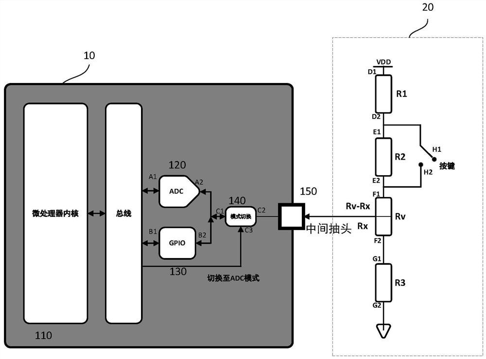
The invention discloses a control circuit, method and system applied to a potentiometer and electronic equipment, and the circuit comprises a single-chip microcomputer and the potentiometer, the first end of a first resistor R1 on the potentiometer is connected with a power supply end, the second end of the first resistor R1 is connected with the first end of a second resistor R2, the second end of the second resistor R2 is connected with the first fixed end of a variable resistor Rv, and the first fixed end of the variable resistor Rv is connected with the single-chip microcomputer. A second fixed end of the variable resistor Rv is connected with a first end of a third resistor R3, and a second end of the third resistor R3 is grounded; a first contact of the key is connected with a first end of the second resistor R2, and a second contact of the key is connected with a second end of the second resistor R2; a center tap of the variable resistor Rv is connected with the input pin; and the single-chip microcomputer is used for collecting the voltage at the input pin and determining the key state. According to the application, through one input pin on the single-chip microcomputer, the potentiometer function can be realized, and the key function can also be realized, so that the number of occupied pins on the single-chip microcomputer is reduced.

Description

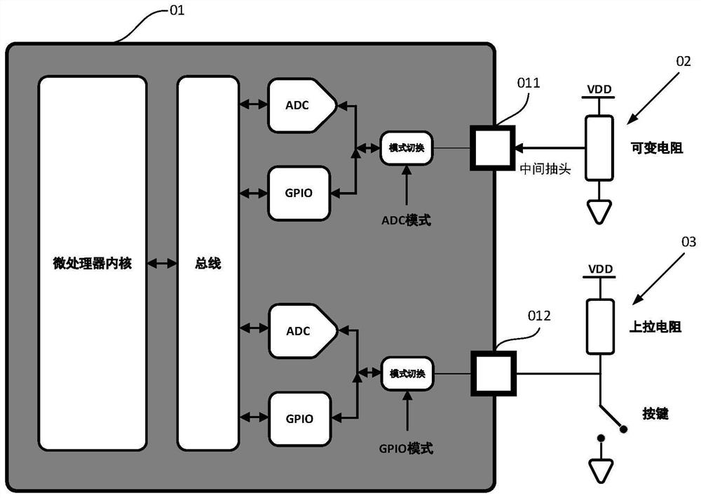
Technical field [0001] This application belongs to the technical field of chip, and more particularly to a control circuit, method, system, and electronic device applied to a potentiometer. Background technique [0002] Single chip microcomputer is a common electronic component. In general, the single chip is integrated with high-precision (typically 10BITS ~ 12BITS) analog-to-digital converter (also known as ADC), which is used to collect some of the analog quantities in circuit schemes. For example, an analog input used to acquire a volume potentiometer; in addition, the button is also a common application in a single chip microcomputer. [0003] figure 1 A structural diagram of a single-chip microcontroller including a potentiometer and a button, such as figure 1 As shown, the single-chip 01 includes two pins, which are first pin 011 and second pins 012, where the first pin 011 is connected to the potentiometer 02, and the second pin 012 is connected to the button 03. [0004...

Claims


Application Information

Patent Timeline
Patent Type & Authority Applications(China)
IPC IPC(8): G05B19/042
Inventor 陈殿玉顾延珂张仁
Owner 北京允芯微电子有限公司
Learn More