Power distribution cabinet door with high-temperature self-locking function

A technology for power distribution cabinets and cabinet doors, which is applied in the layout of substation/power distribution device shells, electrical components, and wing fans, can solve problems such as inability to conduct induction, inability to cool the inside of the distribution cabinet, and inability to seal the cabinet doors. Achieve the effect of avoiding flame entry, increasing safety, and avoiding damage

Pending Publication Date: 2022-04-12
张宝兴
View PDF0 Cites 1 Cited by
  • Summary
  • Abstract
  • Description
  • Claims
  • Application Information

AI Technical Summary

Problems solved by technology

[0005] The purpose of the present invention is to provide a high-temperature self-locking power distribution cabinet door to solve the problems in the above-mentioned background technology that induction self-locking cannot be performed, the cabinet door cannot be sealed, and the temperature inside the power distribution cabinet cannot be cooled.

Method used


Image

  • Power distribution cabinet door with high-temperature self-locking function
  • Power distribution cabinet door with high-temperature self-locking function
  • Power distribution cabinet door with high-temperature self-locking function

Examples


Embodiment 1

[0027] as attached figure 1 to attach Figure 6 Shown:

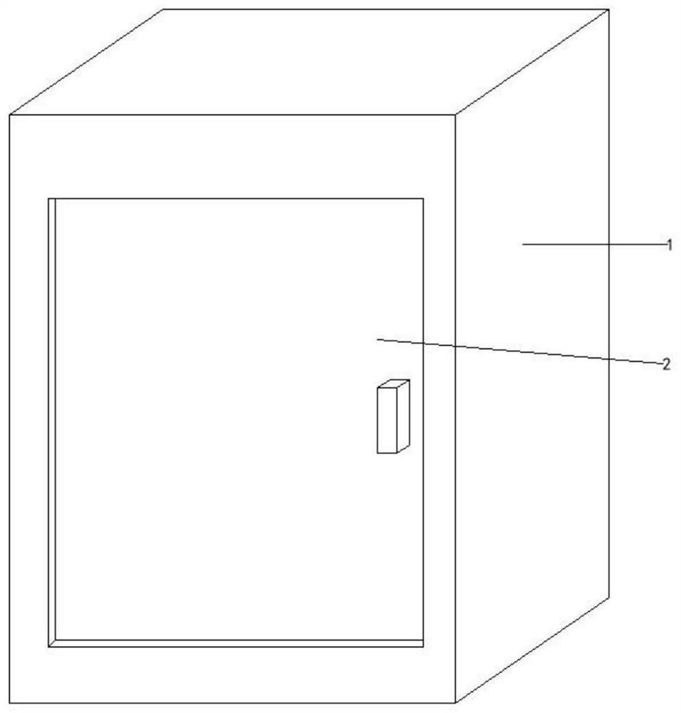
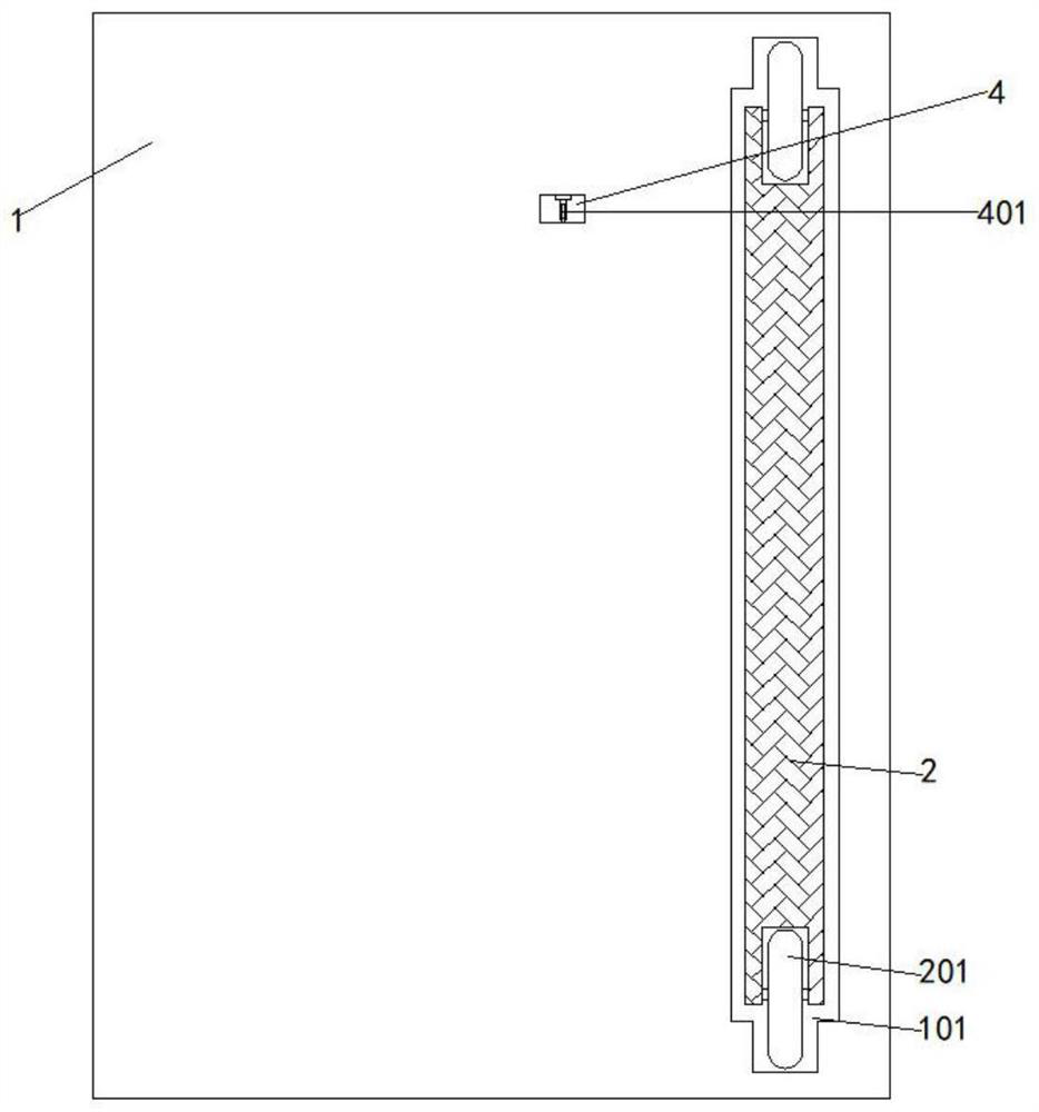
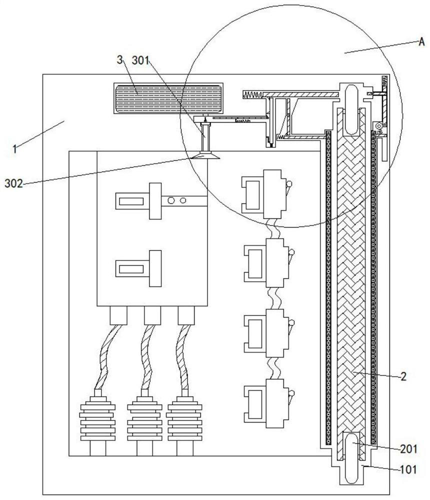
[0028] The present invention provides a high-temperature self-locking power distribution cabinet door, the high-temperature self-locking power distribution cabinet door includes: power distribution cabinet 1, chute 101, cabinet door 2 and pulley 201, inside the power distribution cabinet 1 A chute 101 is provided at the top and bottom of one side, and a cabinet door 2 is slid between the two chute 101 through a pulley 201 . The inside of the power distribution cabinet 1 is respectively provided with a self-locking structure and a sealing structure.

[0029] as attached figure 2 , 3 , 4, 5, and 6, wherein the self-locking structure includes: a groove A4, a glass tube 401, a slider A402, a triangular block A403, a groove C407, a block 408 and a triangular block C409, wherein the power distribution One side of the cabinet 1 is hollow with a groove A4, and the bottom of the groove A4 is fixedly installed with a glass tu...

Embodiment 2

[0035] as attached image 3 , 4 , 5, the present invention also includes a cooling structure, the cooling structure is located in the middle of the power distribution cabinet 1, the cooling structure includes: carbon dioxide storage box 3, injection pipe 301, opening and closing valve 3011, injection port 302, groove B404, The slider B405 and the soft hook 406, wherein the carbon dioxide storage box 3 is fixedly installed in the middle of the upper part of the power distribution cabinet 1, the injection pipe 301 is fixedly installed under the carbon dioxide storage box 3, and the opening and closing valve 3011 is nested outside the injection pipe 301, and The opening and closing valve 3011 switch extends into the groove B404, and the groove B404 and the opening and closing valve 3011 switch are located on the same horizontal plane, and the injection port 302 is fixedly installed under the injection pipe 301, and the injection port 302 is located above the inside of the power d...


PUM


Abstract

The invention provides a power distribution cabinet door with a high-temperature self-locking function, which comprises a power distribution cabinet, sliding grooves, a cabinet door and pulleys, the sliding grooves are formed in the upper part and the lower part of one side in the power distribution cabinet, the cabinet door is slidably arranged between the two sliding grooves through the pulleys, and a self-locking structure and a sealing structure are respectively arranged in the power distribution cabinet. The self-locking structure comprises a groove A, a glass tube, a sliding block A, a triangular clamping block A, a groove C, a clamping block and a triangular clamping block C. The groove A is formed in one side of the power distribution cabinet in a hollow mode, the glass tube is fixedly installed at the bottom of the groove A, and the sliding block A is connected into the groove A through a spring. Through arrangement of a groove A, a glass tube, a sliding block A, a triangular clamping block A, a groove C, a clamping block and a triangular clamping block C, the glass tube can be heated and broken when a fire disaster occurs outside, so that a series of linkage reactions occur, the clamping block extends out to block a pulley at a cabinet door, flame cannot enter the power distribution cabinet to damage the power distribution cabinet, and the safety is improved.

Description

technical field [0001] The invention relates to the technical field of power distribution cabinets, in particular to a high-temperature self-locking power distribution cabinet door. Background technique [0002] The power distribution cabinet (box) is divided into power distribution cabinet (box), lighting distribution cabinet (box), metering cabinet (box), and is the final equipment of the power distribution system. The cabinet is used in the occasions where the load is relatively scattered and there are few circuits. The motor control center is used in the occasions where the load is concentrated and there are many circuits. They distribute the electric energy of a certain circuit of the upper-level power distribution equipment to the nearby load. The load provides protection, monitoring and control, and the protection of the distribution cabinet is very important. [0003] Because the existing power distribution cabinet door cannot be self-locked by induction when a fire...

Claims


Application Information

Patent Timeline
Patent Type & Authority Applications(China)
IPC IPC(8): H02B1/38H02B1/28A62C3/16E05C19/00E06B3/46E06B7/18
Inventor 张宝兴
Owner 张宝兴
Why Eureka
Try Eureka