
Fixing structure based on smart power grid cable and mounting method

A fixed structure and smart grid technology, applied in the direction of cable suspension device, cable laying equipment, overhead line/cable equipment, etc., can solve the problems of high use limitation, damage, and inability to rotate the cable, so as to improve the use effect and prolong the life of the cable. The effect of increasing the service life and improving the limitation of use

Pending Publication Date: 2022-04-12
国网黑龙江省电力有限公司管理培训中心 +2
View PDF0 Cites 2 Cited by
  • Summary
  • Abstract
  • Description
  • Claims
  • Application Information

AI Technical Summary

Problems solved by technology

[0003] At present, most of the fixing devices in the prior art use clamps to fix the cable, and the angle of the cable after fixing is usually unable to rotate, which leads to the fact that the cable is prone to damage due to the need for torsion during actual use. High limitations, can not meet the needs of users

Method used


Image

  • Fixing structure based on smart power grid cable and mounting method
  • Fixing structure based on smart power grid cable and mounting method
  • Fixing structure based on smart power grid cable and mounting method

Examples


Embodiment 1

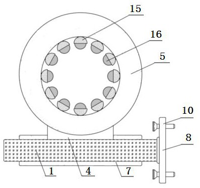
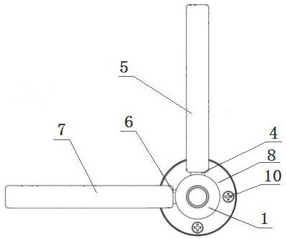
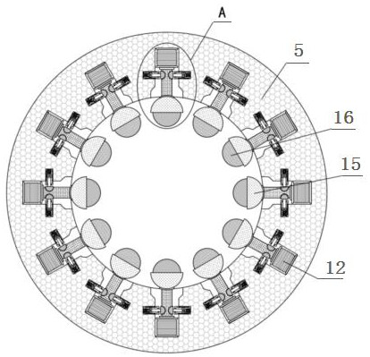
[0026] A fixed structure based on smart grid cables, which consists of: a body 1, a groove 2 is provided on one side of the body, a movable shaft 3 is installed in the groove, and a fixing member is installed on the outside of the body A4, the clamp A5 is fixed on the fixed part A, the fixed part B6 is fixed on the outside of the movable shaft, the clamp B7 is installed on one side of the fixed part B, and the right end of the body is fixed with The mounting plate 8 is provided with four evenly distributed mounting holes 9 on the mounting plate, the mounting holes are provided with fixing bolts corresponding to the mounting holes, and the clamp A and The inside of the clamp B is provided with a mounting groove 11 , and the top of the inner wall of the mounting groove is provided with a mounting air cushion 12 .

Embodiment 2

[0028] According to the fixing structure based on smart grid cables described in Embodiment 1, the lower side of the installation air cushion is fixedly equipped with a movable main rod 13, and the end of the movable main rod far away from the installation air cushion is provided with a clip Tighten the ball 16, the outer side of the clamping ball is equipped with a protective shell 15, the protective shell is hemispherical, the clamping ball is connected with the shaft end of the movable main rod through the protective shell Fixed connection.

Embodiment 3

[0030] According to the fixed structure based on the smart grid cable described in Embodiment 2, the left and right sides of the movable main rod and the inner walls of the clamp A and the clamp B are provided with a limit spring 17, and the limit spring 17 is installed The shaft end of the spring is fixedly connected with a movable connecting rod 18, and a movable clip 19 is fixedly installed at one end of the movable connecting rod opposite to the movable main rod.


PUM


Abstract

The invention relates to an installation method of a fixing structure based on a smart power grid cable. At present, the angle of a fixed cable cannot be rotated generally in the prior art, so that the cable is damaged due to the torsion requirement in actual use, the use limitation is high, and the use requirement cannot be met. A groove (2) is formed in one side of the body, a movable rotating shaft (3) is installed in the groove, a fixing piece A (4) is installed on the outer side of the body, a hoop A (5) is fixed to the fixing piece A, a fixing piece B (6) is fixed to the outer side of the movable rotating shaft, a hoop B (7) is installed on one side of the fixing piece B, an installation disc (8) is fixed to the right end of the body, and four evenly-distributed installation hole positions (9) are formed in the installation disc. Fixing bolts corresponding to the mounting hole positions are arranged on the mounting hole positions, and mounting grooves (11) are formed in the clamp A and the clamp B respectively. The invention is used for the fixing structure based on the intelligent power grid cable.

Description

technical field [0001] The invention relates to a fixed structure and an installation method based on smart grid cables. Background technique [0002] As the pace of China's electric power development continues to accelerate, the smart grid has also developed rapidly, and basically formed a complete long-distance transmission grid structure. At present, the cables of the smart grid are mainly installed on walls or poles through fixtures; [0003] At present, most of the fixing devices in the prior art use clamps to fix the cables when they are in use, and the angle of the cables after fixing is usually unable to rotate, which leads to the fact that the cables are prone to damage due to the need for torsion during actual use. The limitations are high and cannot meet the needs of users. Therefore, improvement is urgently needed. The present application researches and improves the existing structure and defects, and provides a cable fixing structure for smart grid, in order to...

Claims


Application Information

Patent Timeline
Patent Type & Authority Applications(China)
IPC IPC(8): H02G3/04H02G3/30H02G7/05H02G1/04H02G1/06
Inventor 柳新全滕为军邵薇霖郭袅孙立业
Owner 国网黑龙江省电力有限公司管理培训中心
Learn More