
H-bridge mechanical bypass control circuit, control method and system

A bypass control and mechanical technology, applied in flexible AC power transmission systems, circuit devices, emergency protection circuit devices, etc., can solve problems such as affecting the use of SVG, unable to operate SVG normally, and increasing the failure rate of high-voltage SVG.

Pending Publication Date: 2022-04-12
ANHUI USEM TECH CO LTD
View PDF6 Cites 1 Cited by
  • Summary
  • Abstract
  • Description
  • Claims
  • Application Information

AI Technical Summary

Problems solved by technology

The increase in the number of H-bridge power units and the increase in output current will lead to an increase in the failure rate of high-voltage SVG
Once the H-bridge power unit fails, SVG will not be able to operate normally, which will seriously affect the use of SVG

Method used


Image

  • H-bridge mechanical bypass control circuit, control method and system
  • H-bridge mechanical bypass control circuit, control method and system
  • H-bridge mechanical bypass control circuit, control method and system

Examples


Embodiment Construction

[0032] The specific implementation manners of the embodiments of the present invention will be described in detail below in conjunction with the accompanying drawings. It should be understood that the specific implementation manners described here are only used to illustrate and explain the embodiments of the present invention, and are not intended to limit the embodiments of the present invention.

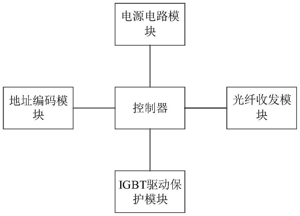
[0033] figure 1 It is a block diagram of a H-bridge mechanical bypass control circuit of the present invention, such as figure 1 As shown, the H-bridge mechanical bypass control circuit includes the following components configured on each power unit: a controller, an IGBT drive protection module and a power circuit module electrically connected to the controller; wherein, the IGBT The drive protection module is connected to the contactor installed on the power unit where it is located, and is used to receive control information from the controller to drive the contactor to close ...


PUM


Abstract

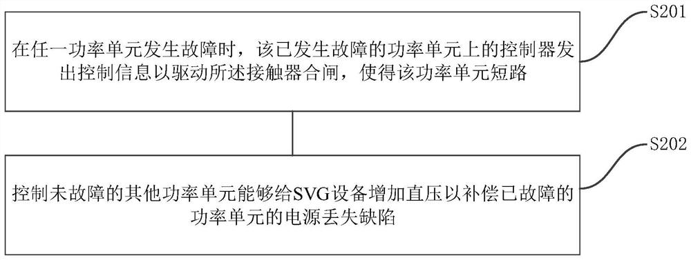
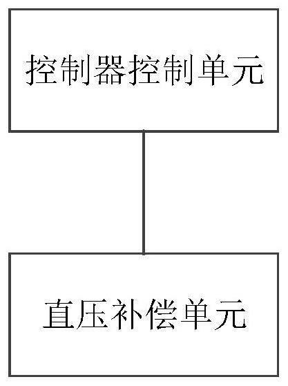
The embodiment of the invention provides an H-bridge mechanical bypass control circuit, control method and system, and belongs to the technical field of high-voltage dynamic reactive compensation. The H-bridge mechanical bypass control circuit comprises the following components configured on each power unit: a controller, and an IGBT driving protection module and a power supply circuit module which are electrically connected with the controller; wherein the IGBT driving protection module is connected to a contactor installed on the power unit where the IGBT driving protection module is located, and is used for receiving control information from the controller to drive the contactor to be switched on when the power unit where the IGBT driving protection module is located fails. The current failed power unit is short-circuited, and other non-failed power units can increase the direct voltage to the SVG equipment so as to compensate the power loss defect of the failed power unit; the power supply circuit module is used for providing working voltage for the controller and the IGBT driving protection module.

Description

technical field [0001] The invention relates to the technical field of high-voltage dynamic reactive power compensation, in particular to an H-bridge mechanical bypass control circuit, control method and system. Background technique [0002] As high-voltage SVG is widely used in steel mills, chemical industry, photovoltaic, wind power and other industries, the demand for high-voltage SVG voltage level and capacity is gradually increasing, and new requirements are also placed on the reliability of high-voltage SVG. The higher the voltage level of the high-voltage SVG, the more the number of H-bridge power units connected in series, and the larger the capacity, the greater the output current of the high-voltage SVG device. The increase in the number of H-bridge power units and the increase in output current will lead to an increase in the failure rate of high-voltage SVG. Once the H-bridge power unit fails, SVG will not be able to operate normally, which will seriously affect...

Claims


Application Information

Patent Timeline
Patent Type & Authority Applications(China)
IPC IPC(8): H02J3/18H02J13/00H02H7/26
CPCY02E40/10
Inventor 桂吉祥张磊陆继文毕孟航石伟夏涵
Owner ANHUI USEM TECH CO LTD
Learn More