
A three-dimensional positioning synchronous tracking camera system and control method

A synchronous tracking and three-dimensional positioning technology, which is applied in the parts of the TV system, image communication, TV and other directions, can solve the problems such as the inaccurate return of the observed object, the inaccurate variable-speed tracking of the camera system, and the low protection ability of the camera system. , to achieve the effect of low cost, low delay and high protection level

Active Publication Date: 2022-07-29
天芯宜智能网络科技(天津)有限公司
View PDF11 Cites 0 Cited by
  • Summary
  • Abstract
  • Description
  • Claims
  • Application Information

AI Technical Summary

Problems solved by technology

[0009] In view of this, the present invention aims to propose a three-dimensional positioning synchronous tracking camera system to solve the problem of the low protection ability of the general camera system under nuclear environmental conditions and the inability of the camera system itself to accurately track the observed object at variable speeds and to accurately predict regression. placement point problem

Method used


Image

  • A three-dimensional positioning synchronous tracking camera system and control method
  • A three-dimensional positioning synchronous tracking camera system and control method
  • A three-dimensional positioning synchronous tracking camera system and control method

Examples


Embodiment 1

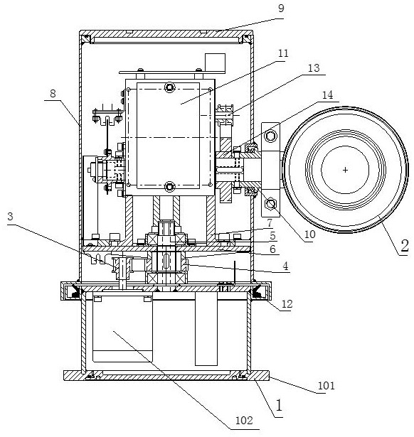
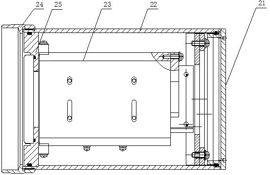
[0076] A three-dimensional positioning synchronous tracking camera system, comprising: a three-dimensional positioning synchronous tracking control board 11, a camera device 2, and a three-dimensional positioning synchronous tracking pan-tilt device 1;

[0077] The 3D positioning synchronous tracking control board 11 and the camera device 2 are both installed on the 3D positioning synchronous tracking PTZ device 1;

[0078] The three-dimensional positioning synchronous tracking pan-tilt includes a rotating disk 6 and a first drive assembly for driving the rotating disk 6 to rotate. The three-dimensional positioning synchronous tracking control board 11 and the camera device 2 are both mounted on the rotating disk 6 through the motor bracket 7;

[0079] The camera device 2 is rotatably mounted on the rotary disk 6 through the second drive assembly.

[0080] The three-dimensional positioning synchronous tracking pan / tilt also includes a lower fixed shell 101 , the first drive as...

Embodiment 2

[0118] like Figures 10 to 12 As shown, a three-dimensional positioning synchronous tracking camera control method includes the following steps:

[0119] S1, according to the three-dimensional coordinates of the tracking camera and the three-dimensional coordinates of the tracked object, calculate the focal length of the tracked object and the single image of the tracking camera;

[0120] S2. According to the focal length of the single-fold image, calculate the zoom value that tracks the change of the camera, and then calculate the coordinate value of the zoom motor corresponding to the zoom value;

[0121] S3, according to the current coordinate value of the zoom motor of the tracking camera, calculate the difference between the predetermined coordinate and the current coordinate of the zoom motor, and calculate the speed of the gimbal according to the difference;

[0122] S4. Calculate the vertical and horizontal angles according to the three-dimensional coordinates of the ...


PUM


Abstract

The invention provides a three-dimensional positioning synchronization tracking camera system, comprising: a three-dimensional positioning synchronization tracking control board, a camera device, and a three-dimensional positioning synchronization tracking pan-tilt device; the three-dimensional positioning synchronization tracking control board and the camera device are both installed on the three-dimensional positioning synchronization tracking cloud further, the 3D positioning synchronous tracking pan / tilt head includes a rotating disk and a first driving component for driving the rotating disk to rotate, and the 3D positioning synchronous tracking control board and the camera device are both installed on the rotating disk through a motor bracket; the camera device The second drive assembly is rotatably mounted on the rotating disk. The three-dimensional positioning synchronous tracking camera system of the present invention has 360° continuous rotation in both the horizontal and vertical directions, variable rotation speed, high positioning accuracy, low delay, and also includes shock resistance and IP66 protection level and high stability. , the characteristics of low cost.

Description

technical field [0001] The invention belongs to the technical field of three-dimensional positioning synchronous tracking video monitoring, and in particular relates to a three-dimensional positioning synchronous tracking camera system and a control method. Background technique [0002] As an important industry with harsh environment, the nuclear ring crane operation area strictly monitors the production operation area to effectively ensure the safe and orderly progress of production, detect abnormal conditions in time, and stop the abnormal process in the bud. [0003] In most monitoring projects on the market at present, the camera system will be installed in an indoor or outdoor ordinary environment and observed at a fixed point, so the camera system needs to have a basic fixed-speed rotational motion. However, due to the complexity of the working environment of the nuclear environment site, and the need for the camera system to automatically aim at the observation target...

Claims


Application Information

Patent Timeline
Patent Type & Authority Patents(China)
IPC IPC(8): H04N5/232F16M11/18F16M11/10F16M11/08
Inventor 孙元杰殷亚雷崔巍张旺邵霞
Owner 天芯宜智能网络科技(天津)有限公司
Learn More