Wind turbine blade with gurney flap
A technology of wind turbines and Gurney flaps, applied in the field of Gurney flaps, can solve the problems of failure, large bending force, difficult application, etc.
- Summary
- Abstract
- Description
- Claims
- Application Information
AI Technical Summary
Problems solved by technology
Method used
Image
Examples
Embodiment Construction
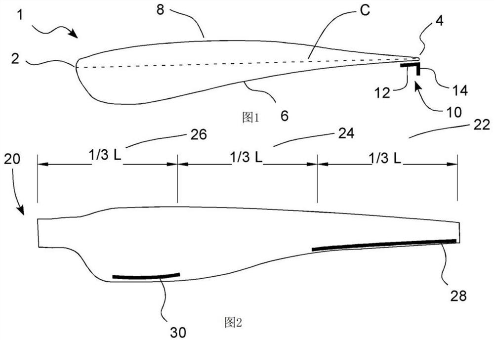
[0042] figure 1 A cross-sectional view of a conventional airfoil 1 of a wind turbine blade is shown. The airfoil has a leading edge 2 , a trailing edge 4 , a chord C connecting the leading edge 2 and the trailing edge, a pressure surface 6 and a suction surface 8 . A detailed description of how the airfoil works will not be discussed here, as it is expected that those skilled in the art will be familiar with the theory behind the airfoil.
[0043] On the pressure surface 6, close to the trailing edge 4, a typical Gurney flap 10 is placed. This is known as Gurney flap positioning. The Gurney flap in this embodiment comprises a first flange 12 attached to the pressure surface of the blade and a second flange 14 extending perpendicular to the first flange and away from the pressure surface. Within the scope of the invention, the Gurney flaps can be placed in different positions and formed in different ways.
[0044] figure 2 A bottom view of a wind turbine blade 20 is schem...
PUM
 Abstract
Description
Claims
Application Information
 - Generate Ideas
- Intellectual Property
- Life Sciences
- Materials
- Tech Scout
- Unparalleled Data Quality
- Higher Quality Content
- 60% Fewer Hallucinations
Browse by: Latest US Patents, China's latest patents, Technical Efficacy Thesaurus, Application Domain, Technology Topic, Popular Technical Reports.
© 2025 PatSnap. All rights reserved.Legal|Privacy policy|Modern Slavery Act Transparency Statement|Sitemap|About US| Contact US: help@patsnap.com


