Spraying equipment for surface of pressure gauge shell
A technology of shell surface and spraying equipment, which is applied in the direction of surface coating liquid device, pretreatment surface, coating, etc., can solve the problems of inability to accelerate air drying, low efficiency, time-consuming, etc., to reduce the use of manpower, speed up Efficiency and time-saving effects
- Summary
- Abstract
- Description
- Claims
- Application Information
AI Technical Summary
Problems solved by technology
Method used
Image

Examples
Embodiment 1
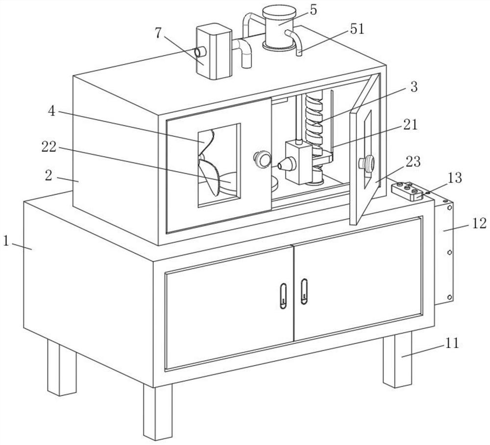
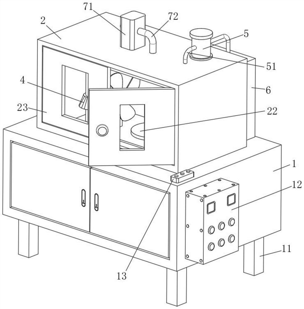
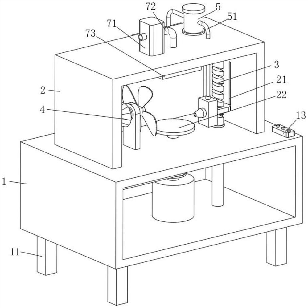
[0030] refer to Figure 1-5 , a spraying equipment for the surface of the pressure gauge shell, including a placing table 1, a protective cover 2 is fixedly installed on the upper surface of the placing table 1, and the action during the spraying process is protected, and the inside of the protective cover 2 is provided with a spraying assembly 3 , the inside of the protective cover 2 is provided with an air-drying assembly 4, and a pressure pump 5 is fixedly installed on the upper surface of the protective cover 2 to facilitate the extraction of the liquid in the liquid storage tank 6. The outlet of the pressure pump 5 is connected with a hose 51 for transporting The liquid reaches the nozzle 39, and the inlet of the pressure pump 5 is connected with a liquid storage tank 6 through a pipeline for storing the liquid required for spraying, and the liquid storage tank 6 is fixedly installed on the upper surface of the placement table 1, and the inside of the protective cover 2 is...
Embodiment 2
[0035] Such as Figure 1-5 As shown, this embodiment is basically the same as Embodiment 1. Preferably, four sets of legs 11 are fixedly installed on the lower surface of the placing platform 1 to support the placing platform 1, and a control box 12 is fixedly installed on one side of the placing platform 1. A button 13 is fixedly installed on the upper surface of the placing table 1 .
[0036] In this embodiment, by setting the control box 12 and the button 13, the automatic spraying of the casing of the pressure gauge is realized, thereby saving the spraying time.
Embodiment 3
[0038] Such as Figure 1-5 As shown, this embodiment is basically the same as Embodiment 1. Preferably, the inner wall of the protective cover 2 is provided with a chute 21, and a disc 22 is provided directly below the protective cover 2, which is convenient for placing the pressure gauge casing, and the lower part of the disc 22 The surface is fixedly connected with the upper end of the output shaft of the motor 31, and the outer surface of the protective cover 2 is hinged with two groups of observation doors 23.
[0039] In this embodiment, by setting the observation door 23, the spraying situation of the pressure gauge casing can be observed at all times, which is convenient for stopping at any time.
PUM
 Abstract
Description
Claims
Application Information
 - R&D Engineer
- R&D Manager
- IP Professional
- Industry Leading Data Capabilities
- Powerful AI technology
- Patent DNA Extraction
Browse by: Latest US Patents, China's latest patents, Technical Efficacy Thesaurus, Application Domain, Technology Topic.
© 2024 PatSnap. All rights reserved.Legal|Privacy policy|Modern Slavery Act Transparency Statement|Sitemap