Optical glass cleaning device

A technology for optical glass and cleaning devices, which is applied in the direction of cleaning flexible objects, cleaning methods and utensils, cleaning methods using tools, etc., can solve problems such as affecting the use of multiplexers and being stained with dust, and achieve the effect of improving the use effect

Active Publication Date: 2022-04-15
JIANGSU ETERN OPTOELECTRONICS TECH CO LTD
View PDF2 Cites 2 Cited by
  • Summary
  • Abstract
  • Description
  • Claims
  • Application Information

AI Technical Summary

Problems solved by technology

[0005] In order to make up for the deficiencies of the existing technology, the optical glass will be in contact with the dust in the air during the transportation of the optical glass. At this time, the surface of the optical glass will be stained with dust. When the optical glass is installed on the multiplexer, it will be The surface of the optical glass is stained with dust, causing problems affecting the use of the multiplexer. This invention proposes a high-performance dense wavelength division multiplexer optical glass

Method used


Image

  • Optical glass cleaning device
  • Optical glass cleaning device
  • Optical glass cleaning device

Examples


Embodiment approach

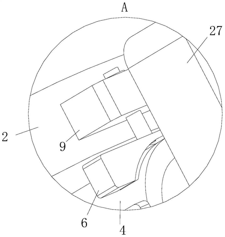
[0030] As an embodiment of the present invention, a fixed block 9 is fixedly connected to the side of the fixed ring 2 close to the rectangular groove 3, and an insertion rod 8 is slidably connected to the inside of the fixed block 9, and the insertion rod 8 is close to the sliding post. One end of 4 is fixedly connected to the limit block 6, and the side of the limit block 6 close to the sliding column 4 is arc-shaped; during work, by pulling the insertion rod 8, the insertion rod 8 drives the limit block 6 to slide, so that The limit block 6 is no longer in contact with the sliding column 4, then let the sliding column 4 slide in the rectangular groove 3, and then slide the sliding column 4 back to its original position, at this time, push the insertion rod 8, so that the insertion rod 8 pushes the limit block 6. At this time, the limiting block 6 will block the sliding column 4, which plays a role of limiting the sliding column 4.

[0031] As an embodiment of the present in...


PUM


Abstract

The invention belongs to the field of optical glass, and particularly relates to an optical glass cleaning device which comprises an optical glass body. A fixing ring is fixedly connected to the side wall of the optical glass body, a rectangular groove is formed in one side of the fixing ring, a sliding column is slidably connected to the inner wall of the rectangular groove, a rotating column is rotatably connected into the sliding column, an arc-shaped plate is fixedly connected to the end, away from the sliding column, of the rotating column, and a sponge block is arranged on the side, close to the rotating column, of the arc-shaped plate; by rotating an arc-shaped plate, the arc-shaped plate drives a sponge block to rotate, at the moment, the sponge block does not make contact with a fixing ring any more, the sponge block can move to the optical glass body, at the moment, due to the flexibility of the sponge block, the sponge block deforms and makes contact with the optical glass body, and therefore the sponge block makes contact with the optical glass body; and a sponge block is arranged, so that dust on the optical glass body is cleaned by the sponge block, the optical glass body is cleaned, and the use effect of the optical glass body is improved.

Description

technical field [0001] The invention relates to the field of optical glass, in particular to an optical glass cleaning device. Background technique [0002] Optical glass is an optical device that can make the imaging of objects darker. [0003] The current high-performance dense wavelength division multiplexer needs to be installed with optical glass to adjust the imaging darkness of the object through the optical glass. [0004] During the transportation of the optical glass, the optical glass will be in contact with the dust in the air. At this time, the surface of the optical glass will be stained with dust. When the optical glass is installed on the multiplexer, the dust on the surface of the optical glass will cause It affects the use of the multiplexer. Therefore, a high-performance dense wavelength division multiplexer optical glass is proposed to solve the above problems. Contents of the invention [0005] In order to make up for the deficiencies of the existing...

Claims


Application Information

Patent Timeline
Patent Type & Authority Applications(China)
IPC IPC(8): B08B1/04B08B11/00B08B1/00B08B13/00
CPCY02P40/57
Inventor 王之琦蒋延标李文强
Owner JIANGSU ETERN OPTOELECTRONICS TECH CO LTD
Why Eureka
Try Eureka