Feed processing and puffing device

An extruding device and feed processing technology, applied in feed, chemical instruments and methods, solid separation, etc., can solve the problems of raw material agglomeration, hopper blockage, etc., and achieve the effect of improving use efficiency, avoiding blockage, and improving cleaning effect.

Active Publication Date: 2022-02-18
江西博美莱生物科技有限公司
View PDF6 Cites 1 Cited by
  • Summary
  • Abstract
  • Description
  • Claims
  • Application Information

AI Technical Summary

Problems solved by technology

[0005] In order to make up for the deficiencies of the existing technology and solve the problem that the raw materials will be agglomerated after being stirred, and the agglomerated raw materials will directly enter the hopper from the discharge port and easily cause the hopper to be blocked. This invention proposes a feed processing extruder device

Method used


Image

  • Feed processing and puffing device
  • Feed processing and puffing device
  • Feed processing and puffing device

Examples


Embodiment 1

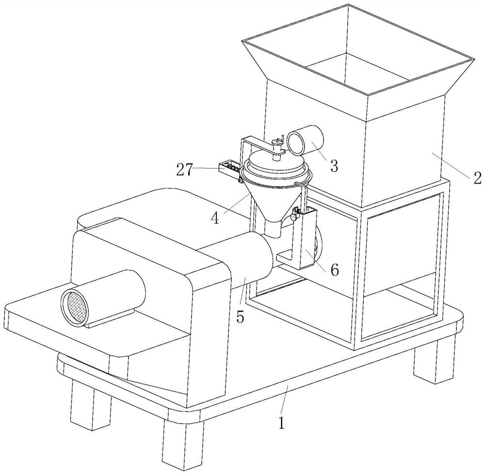
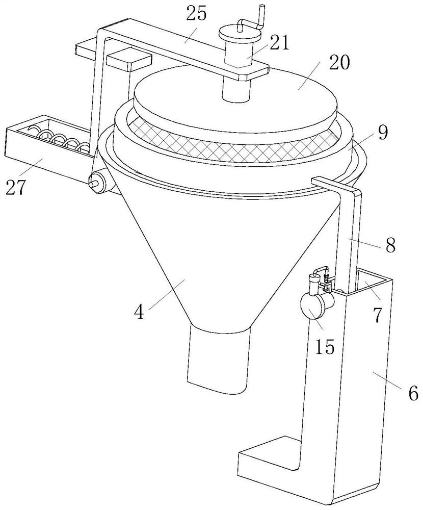
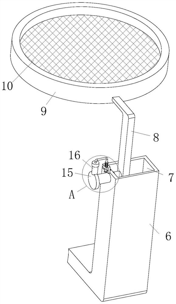
[0027] see Figure 1-5As shown, a feed processing puffing device includes a base plate 1 and a mixer 2; the mixer 2 is installed on the top of the base plate 1 by means of a bracket, and one side of the mixer 2 is connected with a discharge port 3 and a feeding pipe 5, so The feeding pipe 5 is connected with a hopper 4, the surface of the feeding pipe 5 is fixedly connected with a support block 6, and the support block 6 is "L" shaped, and the long arm end of the support block 6 is provided with a chute 7 , the inner wall of the chute 7 is slidingly connected with a slider 8, the slider 8 is "L" shaped, and the short arm end of the slider 8 is fixedly connected with a connecting ring 9, and the inner wall of the connecting ring 9 is fixed Connected with a screen 10, one side of the support block 6 is inserted with an electric telescopic rod 19, and the side of the slider 8 corresponding to the electric telescopic rod 19 is provided with a card slot, and one end of the electric...

Embodiment 2

[0036] see Figure 6 As shown in Comparative Example 1, as another embodiment of the present invention, the sliding plate 25 is slidingly connected to the limiting plate 24; when working, by pulling the round rod 21, the round rod 21 drives the cleaning disc 20 to slide upward, Then the limiting plate 24 is promoted, so that the limiting plate 24 blocks the cleaning disc 20, so that the limiting disc 22 is limited by the blocking of the limiting plate 24, which plays the role of limiting the cleaning disc 20, and then pulls the limiting plate plate 24, so that the limiting plate 24 no longer blocks the cleaning tray 20, and then the cleaning tray 20 is moved.

[0037] The working principle is that by pulling the limit block 31, the limit block 31 no longer blocks the connection plate 14. At this time, the first spring 12 will push the disc 11 due to the recovery of the elastic force, so that the disc 11 will drive the slider 18 to slide upwards. , the slide rod 18 will drive ...


PUM


Abstract

The invention belongs to the field of feed processing, and particularly relates to a feed processing and puffing device. The feed processing and puffing device comprises a bottom plate and a stirring machine, wherein the stirring machine is installed at the top end of the bottom plate through a support; one side of the stirring machine communicates with a discharging port and a material conveying pipe; a hopper communicates with the interior of the material conveying pipe; a surface of the material conveying pipe is fixedly connected with a supporting block; the supporting block is L-shaped; a sliding groove is formed in a long arm end of the supporting block; and a sliding block is slidably connected to an inner wall of the sliding groove. According to the invention, by starting an electric telescopic rod, the electric telescopic rod drives the sliding block to slide in the sliding groove, a connecting ring can slide along with the sliding block, and at the moment, a screen enables caked raw materials on the screen to shake due to movement of the sliding block, so that the caked feed raw materials on the screen are screened and scattered and fall into the hopper, the effect of screening the caked feed raw materials is achieved, the situation that the hopper is blocked is avoided, and the use efficiency of the hopper is improved.

Description

technical field [0001] The invention relates to the field of feed processing, in particular to a feed processing puffing device. Background technique [0002] The feed needs to be processed by a feed extruder, so that the volume of the feed will expand. [0003] The current feed extruder converts mechanical energy into heat energy when processing feed, and extrudes and extrudes the feed with the heat generated when the machine rotates. [0004] Because the raw materials of the feed need to be stirred by the mixer first, and then fall into the hopper at the outlet, the hopper is connected with the feeding pipe, and the feeding pipe transports the raw materials to the heating place of the extruder for puffing. There will be agglomeration, and the agglomerated raw material directly enters the hopper from the discharge port, which will easily cause the hopper to be blocked. Therefore, a feed processing and extruding device is proposed to solve the above problems. Contents of ...

Claims


Application Information

Patent Timeline
Patent Type & Authority Applications(China)
IPC IPC(8): B02C19/16B02C23/16B07B1/52A23N17/00
CPCB02C19/16B02C23/16B07B1/524A23N17/007B02C2023/165Y02P60/87
Inventor 徐田放黄庆
Owner 江西博美莱生物科技有限公司
Why Eureka
Try Eureka