
Touch area identification method and system of infrared touch screen and electronic equipment

A touch area, infrared touch technology, applied in the direction of electrical digital data processing, data processing input/output process, instruments, etc., can solve the problems of extraction, low efficiency of contact recognition calculation, etc., to improve accuracy, improve Computational efficiency and accuracy, reducing the effect of losing pens with fine pens

Pending Publication Date: 2022-04-15
SHENZHEN HONGHE INNOVATION INFORMATION TECH CO LTD
View PDF0 Cites 0 Cited by
  • Summary
  • Abstract
  • Description
  • Claims
  • Application Information

AI Technical Summary

Problems solved by technology

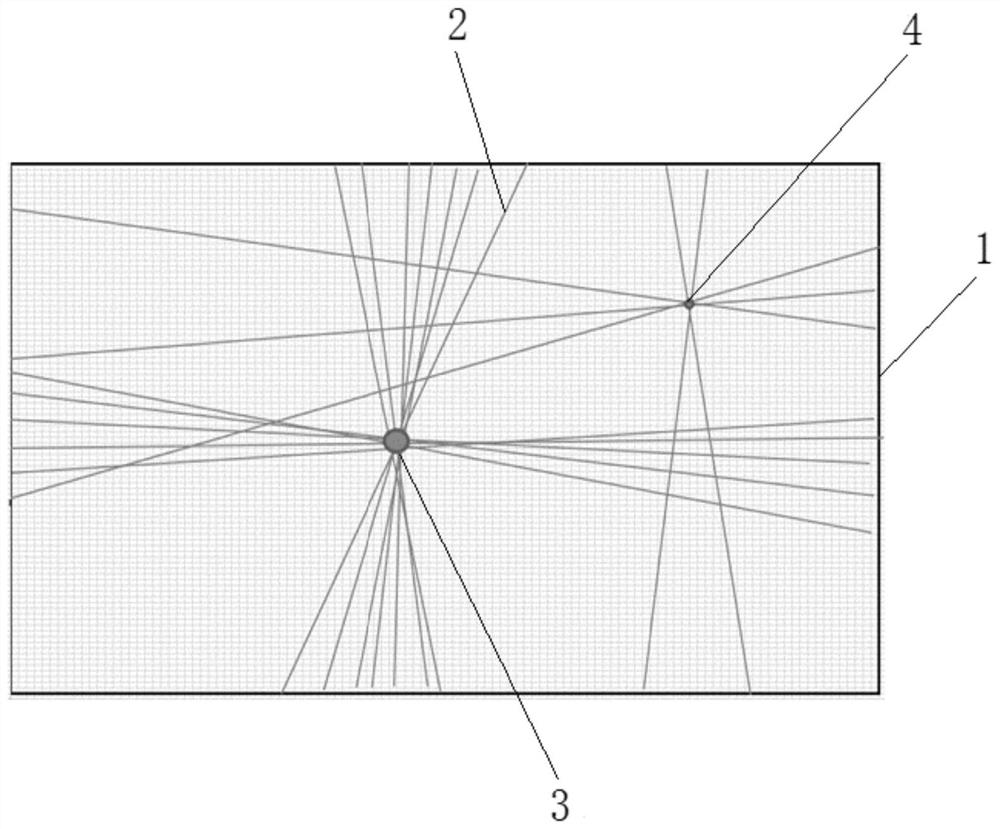
Most of the existing multi-touch touch area recognition methods select the area where several occlusion lines intersect as the touch area, but in fact, due to the existence of multiple infrared light path directions, some occlusion lines will cross when there are multiple touch points. The area is not the real touch area, so it is necessary to extract the intersection area exceeding a certain number of occlusion lines as the touch area by setting the threshold threshold. In this way, larger contacts can be extracted, while smaller contacts (such as thin pen) due to the small number of intersecting occlusion lines, they cannot be extracted at the same time as the larger contacts. After extracting the larger contacts, it is necessary to judge whether all the occlusion lines have passed through the larger contacts, such as If there are still some occlusion lines that do not pass through the larger touch points, the smaller touch points can only be extracted by readjusting the threshold. Point recognition is less computationally efficient

Method used


Image

  • Touch area identification method and system of infrared touch screen and electronic equipment
  • Touch area identification method and system of infrared touch screen and electronic equipment
  • Touch area identification method and system of infrared touch screen and electronic equipment

Examples


Embodiment Construction

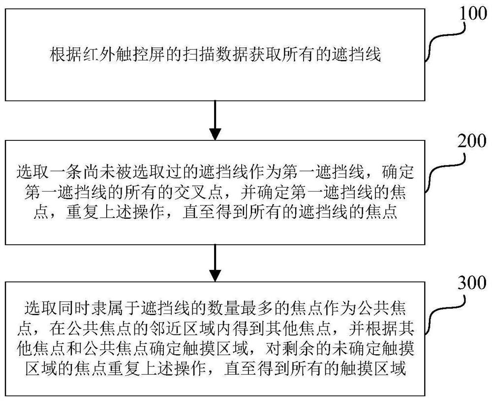
[0069] see figure 1 , the invention provides a method for identifying a touch area of ​​an infrared touch screen, said method comprising the following steps:

[0070] S100, obtain all the occlusion lines according to the scanning data of the infrared touch screen.

[0071] Among them, the infrared touch screen usually includes a number of infrared emitting units and a number of infrared receiving units and their driving circuits installed on the surrounding frame of the touch screen. Under the action of the driving circuit, each infrared emitting unit will Infrared rays are emitted in the direction of the light path, and each infrared receiving unit receives the corresponding infrared rays, thus forming an infrared light network on the screen surface of the touch screen, and detecting and locating the touch of the object by continuously scanning whether the infrared rays are blocked by the object . When a touch-operated object (such as a finger) touches the surface of the sc...


PUM


Abstract

The invention discloses a touch area identification method and system of an infrared touch screen, electronic equipment and a medium, and the method comprises the following steps: obtaining all shielding lines; selecting a shielding line which is not selected as a first shielding line, determining all cross points of the first shielding line, determining a focus of the first shielding line, and repeating the operation until the focuses of all the shielding lines are obtained; and selecting the focus which belongs to the shielding lines at the same time and has the largest number as a common focus, obtaining other focuses in an adjacent area of the common focus, determining a touch area according to the other focuses and the common focus, and repeating the operation on the remaining focuses of which the touch areas are not determined until all the touch areas are obtained. According to the method, the calculation efficiency and accuracy of touch area recognition can be effectively improved.

Description

technical field [0001] The present invention relates to the field of touch technology, in particular to a method, system, electronic device and computer-readable storage medium for identifying a touch area of ​​an infrared touch screen. Background technique [0002] Infrared touch screens usually include a number of infrared emitting units and a number of infrared receiving units and their driving circuits installed on the surrounding borders of the touch screen. Under the action of the driving circuit, each infrared emitting unit will Infrared rays are emitted, and each infrared receiving unit receives corresponding infrared rays, thereby forming an infrared light network on the screen surface of the touch screen. When a touch-operated object (such as a finger) touches the surface of the screen, some infrared rays in the infrared light network will be blocked, and the blocked infrared rays are the blocking lines. The infrared light received by the infrared receiving unit co...

Claims


Application Information

Patent Timeline
Patent Type & Authority Applications(China)
IPC IPC(8): G06F3/041G06F3/042
CPCG06F3/0414G06F3/0416G06F3/0421
Inventor 徐协增汪帅张明华
Owner SHENZHEN HONGHE INNOVATION INFORMATION TECH CO LTD
Learn More