
Cabinet door interlocking device and switch cabinet using same

An interlocking device and switchgear technology, applied in the field of switchgear, can solve the problems of inconvenient opening or closing of the switchgear cabinet door, and easy damage of active parts, so as to ensure the safety of operation, facilitate installation, and realize the reversing function Effect

Pending Publication Date: 2022-04-15
PINGGAO GRP
View PDF0 Cites 0 Cited by
  • Summary
  • Abstract
  • Description
  • Claims
  • Application Information

AI Technical Summary

Problems solved by technology

[0005] The purpose of the present invention is to provide a cabinet door interlocking device to solve the problem that in the prior art, when the distance between the cabinet door and the switch is relatively long, the lengthened active part is easy to cause inconvenience in opening or closing the cabinet door of the switch cabinet, and the active part is easy to be damaged. The technical problem of the operator; the purpose of the present invention is also to provide a switchgear to solve the above technical problem

Method used


Image

  • Cabinet door interlocking device and switch cabinet using same
  • Cabinet door interlocking device and switch cabinet using same
  • Cabinet door interlocking device and switch cabinet using same

Examples


Embodiment 1

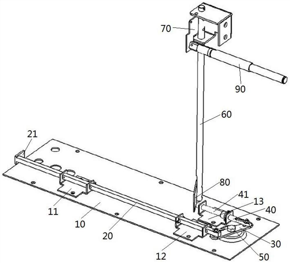
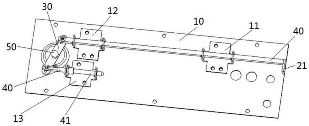
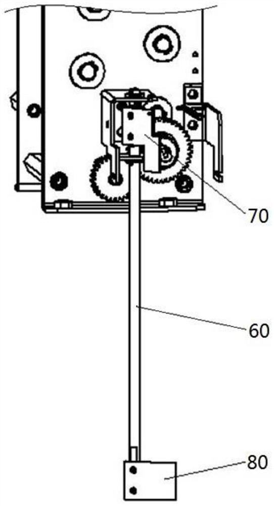
[0040] Such as Figure 4 As shown, the cabinet door interlock device is installed between the cabinet door 100 of the switch cabinet and the switch 120 in the switch cabinet, such as figure 1 and image 3 As shown, the cabinet door interlocking device includes a drive shaft installed on the switch, where the drive shaft is a rotating shaft 60 mounted on the switch, and one end of the rotating shaft 60 is provided with a shielding portion for blocking the switch operating shaft 90, and the rotating shaft 60 The other end is provided with a transmission part. In this embodiment, the shielding part is composed of a single shielding plate 70, and the transmission part is composed of a single transmission plate 80.

[0041] Such as figure 1 and figure 2 As shown, the cabinet door interlocking device also includes a base 10 for being installed on the middle partition 110 in the switch cabinet, a first bracket 11 and a second bracket 12 are installed on the top surface of the bas...

Embodiment 2

[0050] The difference between this embodiment and Embodiment 1 is that in Embodiment 1, a force-bearing plate 21 is provided on the force-bearing end of the push rod 20, that is, pushed by the active part 130 installed on the cabinet door 100 of the switch cabinet. The force plate 21 completes the pushing effect on the push rod 20 . However, in this embodiment, the force receiving plate 21 is omitted, and the force receiving end on the push rod 20 is only one end surface of the push rod 20 .

Embodiment 3

[0052] The difference between this embodiment and Embodiment 1 is that in Embodiment 1, a push rod return spring is provided between the base 10 and the push rod 40, and the push rod return spring is used to make the push rod 40 move away from the position where the cabinet door 100 is located. Direction movement, that is, the reset of the cabinet door interlock device when the cabinet door 100 is opened can be realized by the push rod return spring. However, in the present embodiment, the push rod return spring is canceled, and after opening the cabinet door 100 of the switch cabinet, the cabinet door interlock device is directly reset manually; Resetting of interlocks.


PUM


Abstract

The invention relates to a cabinet door interlocking device and a switch cabinet using the cabinet door interlocking device, the cabinet door interlocking device comprises a transmission shaft, the transmission shaft is provided with a shielding part used for shielding a switch operation shaft, an elastic reset piece is arranged between the shielding part and a switch, a base is installed on a middle partition plate, and a push rod and an ejector rod which extend in parallel are assembled on the base in a guiding mode. The push rod is provided with a stress end; a reversing component of which two ends are respectively connected with or in pushing fit with the ejector rod and the push rod is arranged between the ejector rod and the push rod; the transmission shaft is provided with a transmission part, the transmission part is located between the ejector rod and the cabinet door in the moving direction of the ejector rod, the ejector rod is in pushing fit with or connected with the transmission part so as to push the transmission part to act in the direction where the cabinet door is located when the cabinet door is closed, and the transmission shaft drives the shielding part to move in the direction of avoiding the switch operation shaft. The technical problems that in the prior art, when the distance between the cabinet door and the switch is long, the lengthened driving part is prone to causing the cabinet door of the switch cabinet to be opened or closed inconveniently, and the driving part is prone to bruise operators can be solved.

Description

technical field [0001] The invention belongs to the technical field of switch cabinets, and in particular relates to a cabinet door interlocking device and a switch cabinet using the cabinet door interlocking device. Background technique [0002] In order to improve the safety of the switchgear, when designing the switchgear, it is usually required that the switches (such as isolating switches and handcarts) on the middle partition cannot be closed when the switchgear door is opened, and only after the switchgear door is closed Only then can the closing operation of the switch be carried out. In order to achieve this purpose, a perforation is usually provided on the cabinet door for the handle to pass through. The perforation corresponds to the switch operation shaft of the switch. The staff can pass the handle through the perforation and cooperate with the switch operation shaft after closing the cabinet door to realize the switch. of closing. [0003] In the prior art, a...

Claims


Application Information

Patent Timeline
Patent Type & Authority Applications(China)
IPC IPC(8): H01H9/22
Inventor 冯祥伟卢健唐猛李军辉王海燕张永辉朱彦卿娄源通翟停停李伟令卢留洋朱启媛
Owner PINGGAO GRP
Learn More