Railway energy route regulation and control method for renewable energy microgrid power supply

A renewable energy and routing technology, which is applied in AC network circuits, DC network circuit devices, energy reserves, etc., and can solve the problem that the rated capacity tolerance level of power electronic devices is strictly required, the function of railway energy routers cannot be fully utilized, and the system is not suitable. With local fault tolerance and other problems, to achieve the effect of improving power quality, improving power supply reliability, and eliminating local faults

Active Publication Date: 2022-04-15
SOUTHWEST JIAOTONG UNIV
View PDF9 Cites 4 Cited by
  • Summary
  • Abstract
  • Description
  • Claims
  • Application Information

AI Technical Summary

Problems solved by technology

However, the current research mainly focuses on the centralized photovoltaic energy storage back-to-back converter system. This system does not have local fault tolerance. If some components in the external equipment are abnormal or fail, the overall equipment needs to be cut out of the running state; and The existing system has a large capacity and has strict requirements on the rated capacity and tolerance level of the power electronic devices inside the system
It can be seen that the existing technology cannot give full play to the function of the railway energy router

Method used


Image

  • Railway energy route regulation and control method for renewable energy microgrid power supply
  • Railway energy route regulation and control method for renewable energy microgrid power supply
  • Railway energy route regulation and control method for renewable energy microgrid power supply

Examples


Embodiment Construction

[0042] In order to make the purpose, technical solution and advantages of the present invention clearer, the present invention will be further elaborated below in conjunction with the accompanying drawings.

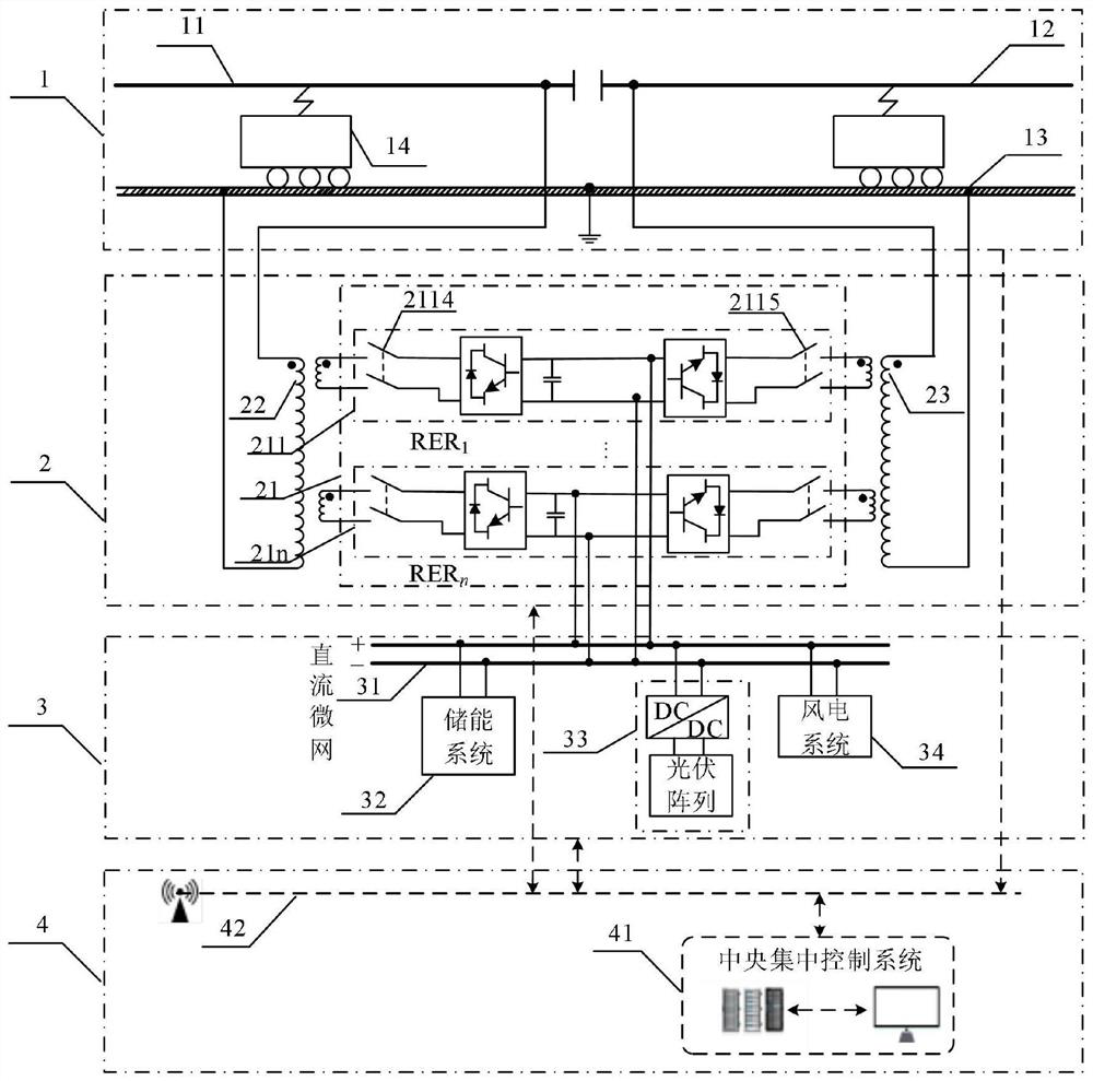
[0043] In this embodiment, the present invention proposes a railway energy routing control method powered by a renewable energy microgrid, which is applied to a railway energy routing system powered by a renewable energy microgrid, and a railway energy routing system powered by a renewable energy microgrid Connected to the traction grid, the railway energy routing system powered by a renewable energy microgrid includes multiple routing subsystems and a DC microgrid, which includes an energy storage system and a renewable energy generation system.

[0044] Such as image 3 As shown, the railway energy routing system 2 powered by the renewable energy microgrid is connected to the traction grid 1 through the primary side of the multi-winding step-down transformer; The DC si...


PUM


Abstract

The invention discloses a renewable energy micro-grid power supply railway energy route regulation and control method, which comprises an energy management layer for switching a current operation mode of a system based on real-time operation data and calculating to obtain a current and/or power instruction compensated by each route subsystem; the regional decision-making layer is used for distributing reference power and/or reference current of each routing subsystem; and the equipment control layer is used for coordinated control of each routing subsystem and the direct-current micro-grid. According to the invention, the regenerative braking energy of the train can be effectively recycled; renewable energy sources are accessed to a traction power supply system, and the energy consumption of a three-phase power grid is reduced; when the traction network has a short-time fault, the power supply capability within a certain period of time can be ensured; the fault-tolerant capability is realized; the electric energy quality problem of a traction power supply system can be effectively improved; and the tolerance requirement on internal power electronic devices in a high-voltage and high-capacity environment can be relieved.

Description

technical field [0001] The invention belongs to the technical field of electrified railways, in particular to a railway energy routing control method for renewable energy micro-grid power supply. Background technique [0002] At present, the world's energy is becoming increasingly tense, and energy conservation and consumption reduction have become a worldwide research topic, while energy recovery and reuse is an effective means of energy conservation and consumption reduction, and the effective use of renewable energy is also a research hotspot in energy conservation and consumption reduction. [0003] With the rapid development of rail transit, the proportion of railway electrification is getting higher and higher, and the regenerative braking energy generated by trains is increasing. When braking or going downhill at a constant speed, the energy flows from the motor to the traction network. If the feedback energy is not fully absorbed, it may cause the traction network vo...

Claims


Application Information

Patent Timeline
Patent Type & Authority Applications(China)
IPC IPC(8): H02J3/00H02J3/06H02J3/28H02J1/00H02J1/14H02J13/00B60M3/00
CPCH02J3/0073H02J3/06H02J3/28H02J1/00H02J1/14H02J13/00001B60M3/00H02J2203/10H02J2300/24H02J2300/28Y02E70/30
Inventor 戴朝华廉静如
Owner SOUTHWEST JIAOTONG UNIV
Why Eureka
Try Eureka