Method for real-time control of exposure at x-ray dose

A real-time control, X-ray technology, applied in the field of radiography, can solve problems such as application flow deterioration

Pending Publication Date: 2022-04-19
特里希尔公司
View PDF1 Cites 0 Cited by
  • Summary
  • Abstract
  • Description
  • Claims
  • Application Information

AI Technical Summary

Problems solved by technology

It also assumes that there is a delay time between the front image and the image, which may worsen the application flow (latency, effect of patient movement, etc.)

Method used


Image

  • Method for real-time control of exposure at x-ray dose
  • Method for real-time control of exposure at x-ray dose
  • Method for real-time control of exposure at x-ray dose

Examples


Embodiment Construction

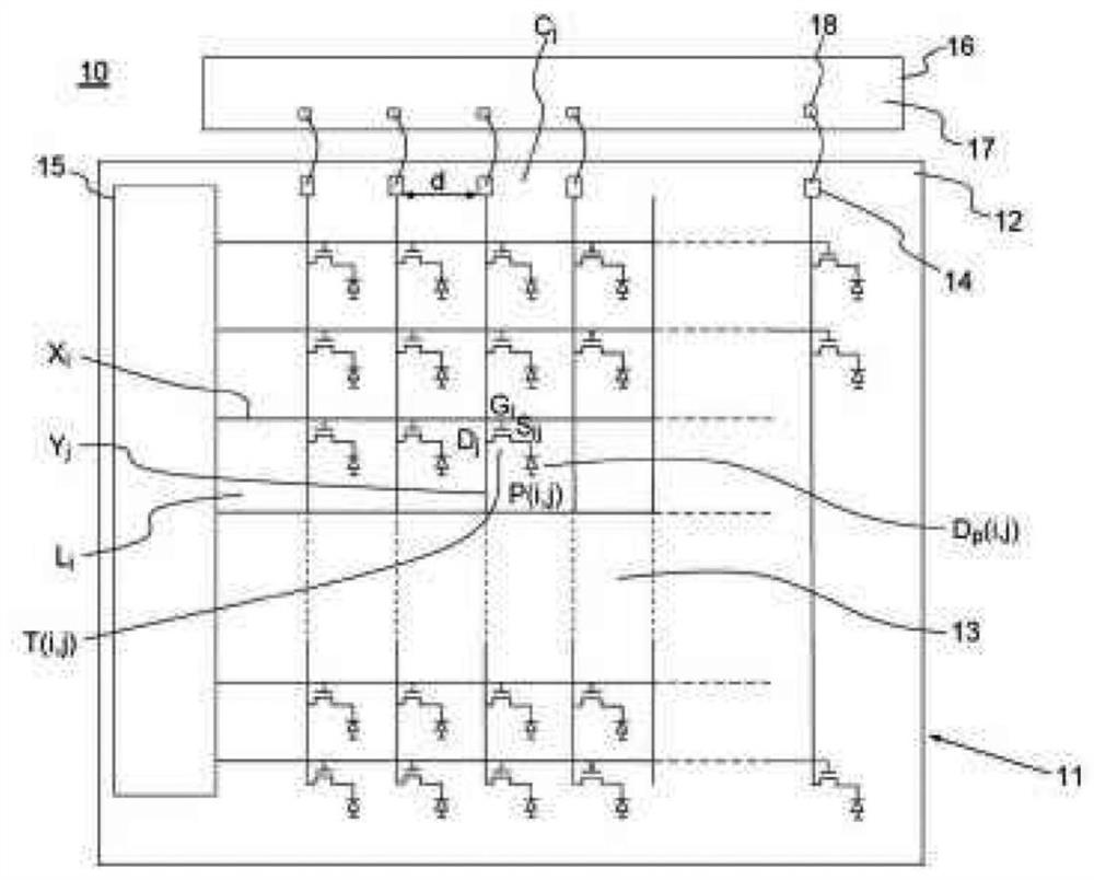
[0056] In general terms, the present invention refers to a conventional image detector, usually comprising a flat panel detector comprising a set of pixels organized in a matrix along rows and columns, row addressable cells , a column readout unit, a row conductor connecting a row of pixels to the row addressing unit, and a column conductor connecting a column of pixels to the column readout unit. It should be noted that, in the context of this patent application, the concepts of column and row have only relative meanings, and a row of pixels and a column of pixels are just rows of pixels arranged, for example (but not limited to), perpendicular to each other. Row conductors or column conductors are defined as being oriented parallel to or oriented to a row of pixels.

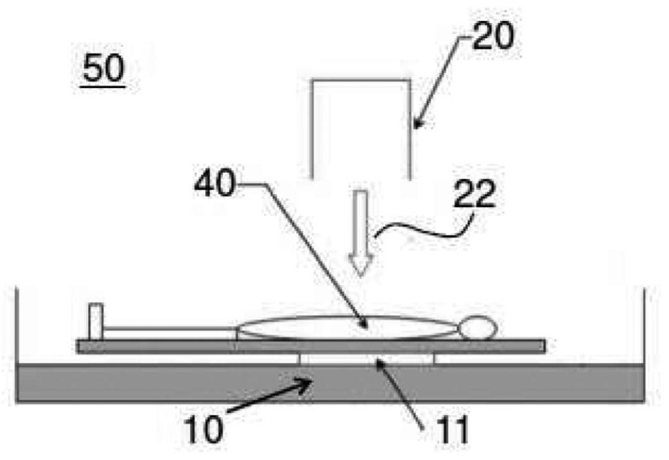
[0057] figure 1 A conventional radiology assembly 50 that has been presented in the background art is schematically shown.

[0058] figure 2 A conventional image detector 10 is shown. The image detector 10...


PUM


Abstract

The present invention relates to a method of real-time control of exposure at an X-ray dose emitted by a generator tube for generating an X-ray beam and received by a detector comprising a flat panel detector comprising: a set of pixels organized in a matrix along rows and columns, a generator tube coupled to the detector and configured to generate a signal based on the X-ray dose impinging on the detector, the generator tube comprising a control unit for controlling the generator tube, the control unit configured to control the emitted X-ray dose; the method is characterized in that it comprises the steps of: exposing the flat panel detector to a dose of X-rays emitted by a generator tube for generating an X-ray beam; repeatedly reading out at least one row of the pixels while the flat panel detector is exposed at the X-ray dose; determining a payload signal and a spurious signal based on the read-out signal from the at least one row; the payload signal is transmitted to a control unit for controlling the generator tube.

Description

technical field [0001] The present invention relates to the technical field of radiography with digital flat panel detectors, and more particularly to equipment for real-time control of exposure levels. Background technique [0002] Exposure parameters (voltage, current, source / patient / detector distances) must be adjusted to minimize the dose received by the patient while still maintaining the best image quality for the radiologist. Optimal exposure parameters depend on the size of the patient, the type of examination desired, and the sensitivity characteristics of the X-ray imager (silver film, PSP plate, digital flat panel detector, etc.). These parameters are typically determined using system software based on indications provided by the radio operator regarding the examination context (size of patient, type of image desired). If these parameters are defined incorrectly (whether due to incorrect or inaccurate indications, or due to incorrect system calibration), there is...

Claims


Application Information

Patent Timeline
Patent Type & Authority Applications(China)
IPC IPC(8): A61B6/00
CPCA61B6/54A61B6/542A61B6/4208H04N5/32H05G1/44H04N25/76A61B6/405A61B6/42A61B6/548A61B6/56G01T1/161A61B6/4233G01T1/17
Inventor T·沃斯B·查尔斯
Owner 特里希尔公司
Why Eureka
Try Eureka