
Detachable new energy automobile power supply battery

A technology of new energy vehicles and power supply batteries, which is applied in the direction of electric vehicles, battery pack parts, battery/battery traction, etc. It can solve the problems of increasing processing costs, prolonging the processing cycle, processing large screw holes in the battery bottom case, etc., to achieve The effect of increasing processing costs

Active Publication Date: 2022-04-19
HUNAN AUTOMOTIVE ENG VOCATIONAL COLLEGE
View PDF8 Cites 0 Cited by
  • Summary
  • Abstract
  • Description
  • Claims
  • Application Information

AI Technical Summary

Problems solved by technology

[0003] The existing new energy vehicle power supply batteries mainly have the following technical defects: First, the assembly method of lithium battery blocks in traditional new energy vehicle power supply batteries is mainly fixed and assembled through a large number of screws, cover shells and card slots. The installation and disassembly of the lithium battery block is too cumbersome. At the same time, the battery bottom case needs to process a large number of screw holes, resulting in a longer processing cycle, which causes inconvenience in disassembly and installation, and increases the processing cost. Second, during the driving process of new energy vehicles, due to The road surface is different and the vehicle is subjected to different levels of bumps. However, there is a certain gap in the assembly of traditional lithium battery blocks, which will cause the lithium battery blocks to shake while the vehicle is bumping, making the lines connected between the lithium battery blocks easy to fall off. At the same time, the lithium battery block is easily damaged when shaking, resulting in the problems of low service life and high maintenance cost of the lithium battery block

Method used


Image

  • Detachable new energy automobile power supply battery
  • Detachable new energy automobile power supply battery
  • Detachable new energy automobile power supply battery

Examples


Embodiment

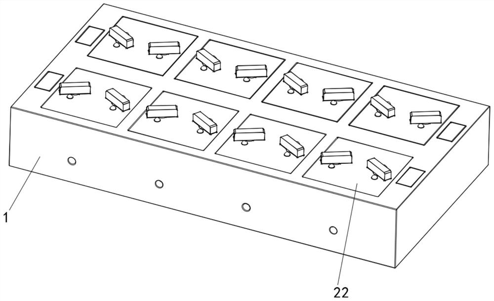
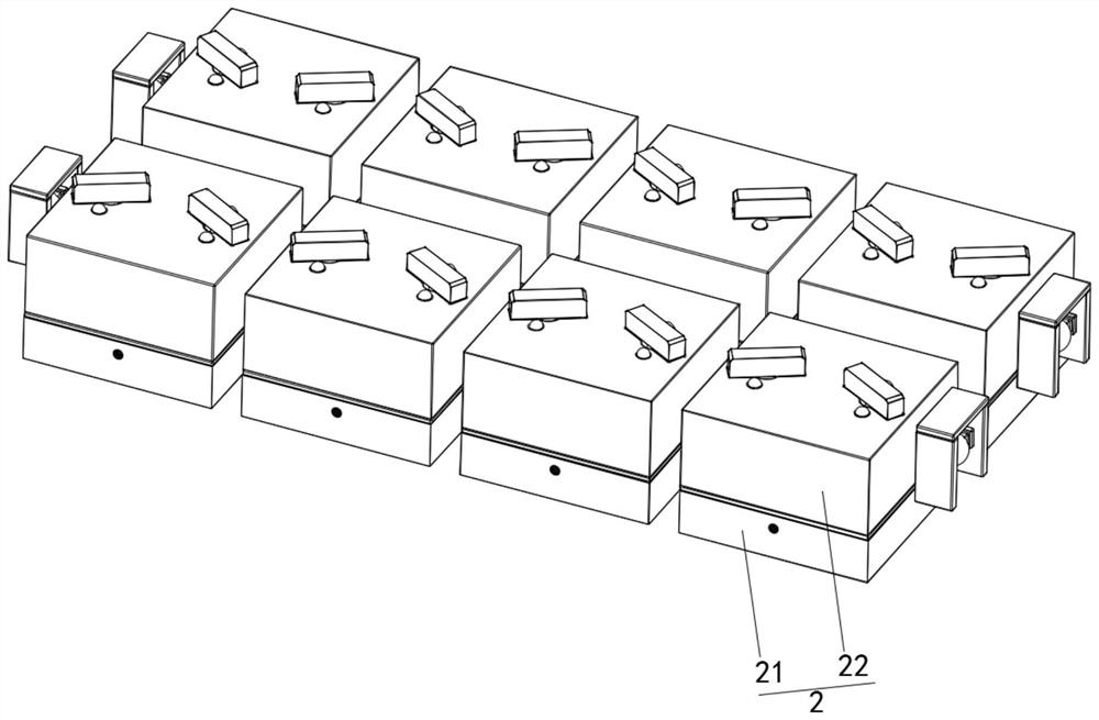
[0036] See Figure 1- Figure 9 , a removable new energy vehicle power supply battery, including the base shell 1, the inner side of the base shell 1 is fixed with a uniformly distributed control device 2, the control device 2 is provided with a resistance device 3, and the base shell 1 is fixedly installed with a detection device 4;

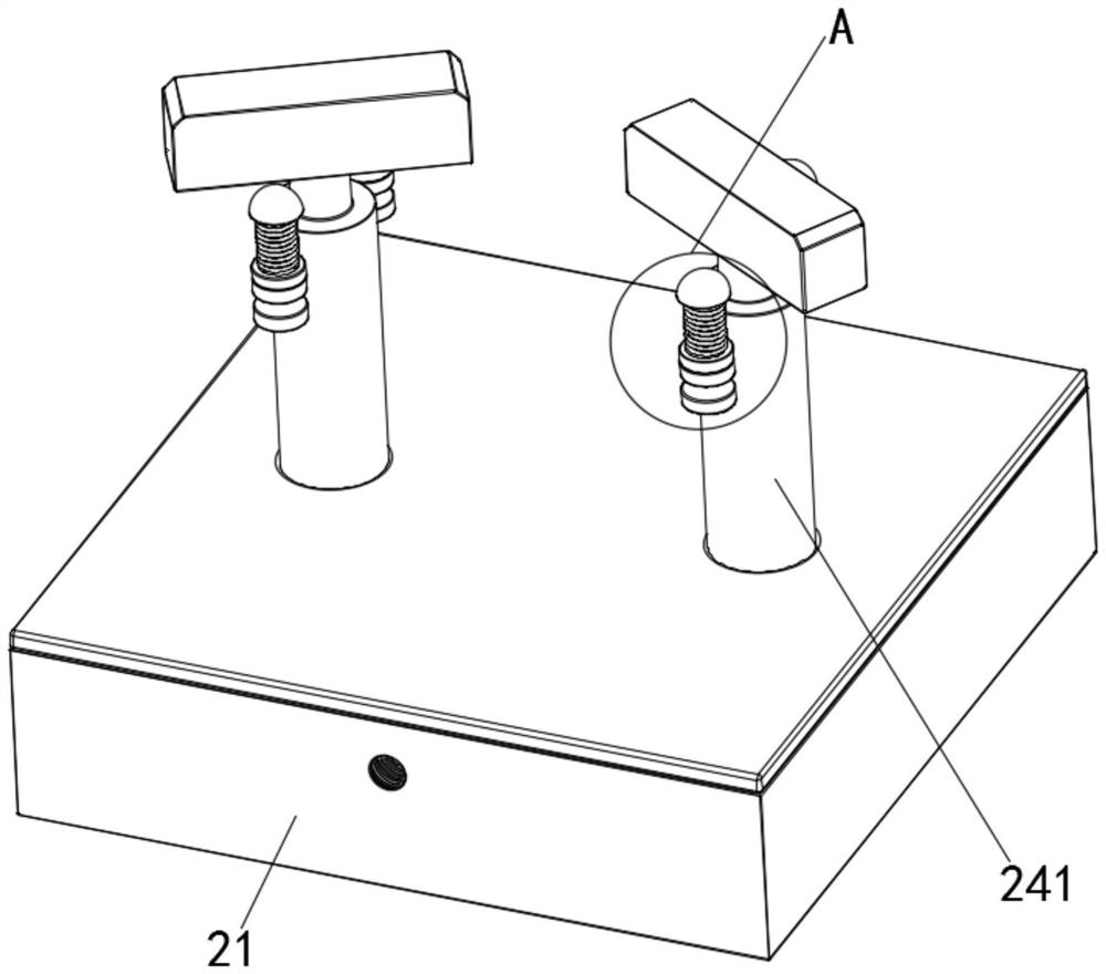
[0037] The control device 2 includes a rectangular housing 21, a battery block 22, a rotating wheel 23, a limiting device 24 and a clamping device 25, the internal fixation of the base housing 1 is connected to a uniformly distributed rectangular housing 21, the upper side of the rectangular housing 21 is provided with a battery block 22, the internal of the rectangular housing 21 is provided with a rotating wheel 23, the rotating wheel 23 is fixedly mounted with a restriction device 24, the internal setting of the rectangular housing 21 is provided with a clamping device 25.

[0038] Further, the structure of the limiting device 24 comprises a contr...


PUM


Abstract

The invention relates to the technical field of new energy automobile batteries, and discloses a detachable new energy automobile power supply battery which comprises a base shell, a control device comprises rectangular shells, battery blocks, rotating wheels, limiting devices and clamping devices, and the rectangular shells which are evenly distributed are fixedly connected into the base shell. And a battery block is arranged on the upper side of the rectangular shell. According to the detachable new energy automobile power supply battery, through the cooperation of the battery block, the base shell, the rectangular shell, the moving block, the fixed block, the connecting rod, the clamping block and the rotating wheel, the problem that the lithium battery block in a traditional new energy automobile power supply battery is fixedly assembled mainly through the cooperation of a large number of screws, a cover shell and a clamping groove is solved; the problems that the lithium battery block is too tedious to mount and dismount due to the mode, and meanwhile, a large number of screw holes need to be machined in the battery bottom shell, so that the machining period is prolonged, dismounting and mounting are inconvenient, and the machining cost is increased are solved.

Description

Technical field [0001] The present invention relates to the field of new energy vehicle battery technology, specifically a removable new energy vehicle power supply battery. Background [0002] With the continuous development of new energy vehicles, lithium batteries as the main source of power for new energy vehicles, new energy power supply batteries are assembled by a plurality of lithium battery blocks, with the continuous development of science and technology, the development trend of new energy vehicle power supply batteries is more and more tending to diversify the direction. [0003] The existing new energy vehicle power supply battery mainly has the following technical defects: First, the assembly mode of lithium battery blocks in traditional new energy vehicle power supply batteries is mainly through a large number of screws, covers and card slots for fixed assembly, which leads to the installation and disassembly of lithium battery blocks being too cumbersome, and the...

Claims


Application Information

Patent Timeline
Patent Type & Authority Applications(China)
IPC IPC(8): B60L50/64H01M50/249H01M50/244
CPCB60L50/64B60L50/66H01M50/249H01M50/244Y02E60/10Y02T10/70Y02T10/7072
Inventor 唐伦邓果露周定武朱先明周礼其他发明人请求不公开姓名
Owner HUNAN AUTOMOTIVE ENG VOCATIONAL COLLEGE
Learn More