Transmission device and application of transmission device in heat dissipation device of power battery pack

A transmission device and rotating block technology, applied in the direction of secondary batteries, circuits, electrical components, etc., can solve the problems of easy cleaning, small space, cumbersome cleaning of blades, etc., and achieve the effect of thorough cleaning, easy cleaning, and damage prevention

Pending Publication Date: 2022-04-19
深圳市福容科技有限公司
View PDF0 Cites 0 Cited by
  • Summary
  • Abstract
  • Description
  • Claims
  • Application Information

AI Technical Summary

Problems solved by technology

[0002] With the continuous improvement of people's awareness of environmental protection, more and more people use new energy vehicles to replace gasoline-burning vehicles. The power battery pack in electric vehicles is the core power supply component, which has a great impact on the service life and driving range of electric vehicles. and other aspects have a great impact. Since the power battery pack will generate a lot of heat during long-term use, in order to ensure the normal operation of the power battery pack, a cooling fan is usually installed in the power battery pack casing. Due to the cooling fan and The casing is an integrated design. When the blades of the cooling fan are covered with a lot of dust due to long-term use, the space available for operation in the casing is very small, and the blades cannot be removed for cleaning, which makes cleaning the blades very cumbersome. And it is easy to clean and not clean, which is not conducive to the heat dissipation of the power battery pack

Method used


Image

  • Transmission device and application of transmission device in heat dissipation device of power battery pack
  • Transmission device and application of transmission device in heat dissipation device of power battery pack
  • Transmission device and application of transmission device in heat dissipation device of power battery pack

Examples


Embodiment Construction

[0030] The following will clearly and completely describe the technical solutions in the embodiments of the present invention with reference to the accompanying drawings in the embodiments of the present invention. Obviously, the described embodiments are only some, not all, embodiments of the present invention.

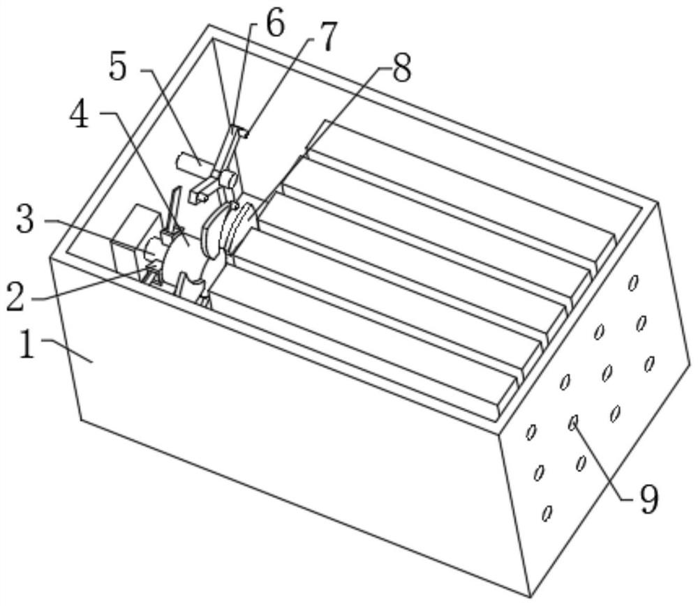
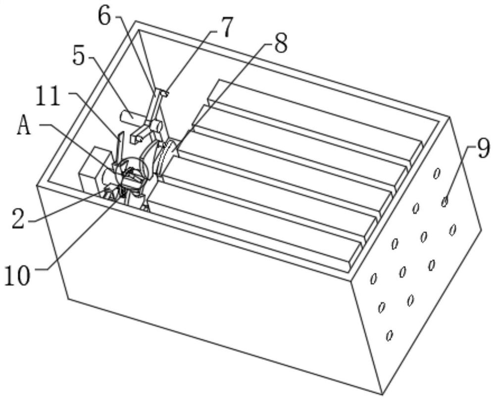
[0031] refer to Figure 1-5 , a transmission device, including a casing 1 and a battery module set in the casing 1, a driving block and a fixed rod 5 are fixedly installed in the casing 1, a rotating shaft 3 is rotatably installed on the driving block, and a rotating shaft 3 is fixedly connected with A plurality of connecting blocks 21, a fixed sleeve 4 is installed on one end of the rotating shaft 3, and a cooling blade 8 is fixedly connected to the fixed sleeve 4, and a rotating sleeve is connected to the fixed rod 5, and a plurality of fan blades 6 are fixedly connected to the rotating sleeve. Gravity blocks 7 are fixedly connected to each fan piece 6, and a plura...


PUM


Abstract

The invention discloses a transmission device which comprises a shell and a battery module arranged in the shell, a driving block and a fixing rod are fixedly installed in the shell, a rotating shaft is rotatably installed on the driving block, a plurality of connecting blocks are fixedly connected to the rotating shaft, a fixing sleeve is installed at one end of the rotating shaft, and the fixing sleeve is fixedly connected to the connecting blocks. The fixing sleeve is fixedly connected with heat dissipation blades, the fixing rod is rotatably connected with a rotating sleeve, the rotating sleeve is fixedly connected with a plurality of fan blades, each fan blade is fixedly connected with a gravity block, and the shell is provided with a plurality of heat dissipation holes. A plurality of clamping blocks used in cooperation with the connecting blocks are fixedly connected to the fixing sleeve. When a lot of dust adheres to the heat dissipation blades, the heat dissipation blades and the fixing sleeve can be detached, so that the heat dissipation blades can be cleaned more conveniently and more thoroughly, and heat dissipation of the power battery pack is facilitated.

Description

technical field [0001] The invention relates to the technical field of power batteries, in particular to a transmission device and its application in a power battery pack cooling device. Background technique [0002] With the continuous improvement of people's awareness of environmental protection, more and more people use new energy vehicles to replace gasoline-burning vehicles. The power battery pack in electric vehicles is the core power supply component, which has a great impact on the service life and driving range of electric vehicles. and other aspects have a great impact. Since the power battery pack will generate a lot of heat during long-term use, in order to ensure the normal operation of the power battery pack, a cooling fan is usually installed in the power battery pack casing. Due to the cooling fan and The casing is an integrated design. When the blades of the cooling fan are covered with a lot of dust due to long-term use, the space available for operation in...

Claims


Application Information

Patent Timeline
Patent Type & Authority Applications(China)
IPC IPC(8): H01M10/613H01M10/625H01M10/6563H01M10/6556
CPCH01M10/613H01M10/625H01M10/6563H01M10/6556Y02E60/10
Inventor 肖云辉肖云亮
Owner 深圳市福容科技有限公司
Why Eureka
Try Eureka