Automatic positioning and marking clamp

An automatic positioning and fixture technology, used in typewriters, printing and other directions, can solve the problems of inability to meet processing, poor adaptability, poor practical performance, etc., to facilitate cleaning and maintenance, increase the range of limit, and facilitate the range of limit. Effect

Active Publication Date: 2022-04-22
无锡市蠡湖铸业有限公司
View PDF4 Cites 0 Cited by
  • Summary
  • Abstract
  • Description
  • Claims
  • Application Information

AI Technical Summary

Problems solved by technology

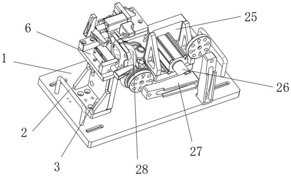
[0004] The object of the present invention is to provide an automatic positioning marking fixture to solve the problem that the existing marking fixture proposed in the background technology cannot It is convenient to install and assemble, and the workpiece cannot be fixed stably at the same time, resulting in the deviation of information such as two-dimensional codes when marking it, which cannot meet the needs of processing, and the structure of each part of the clamp body cannot be flexibly moved. Cooperate, it is not flexible enough to use, the practical performance is poor, and it is impossible to adapt and position special bent pipe-shaped items, and the adaptability is poor

Method used


Image

  • Automatic positioning and marking clamp
  • Automatic positioning and marking clamp
  • Automatic positioning and marking clamp

Examples


Embodiment Construction

[0026] The following will clearly and completely describe the technical solutions in the embodiments of the present invention with reference to the accompanying drawings in the embodiments of the present invention. Obviously, the described embodiments are only some, not all, embodiments of the present invention.

[0027] In the description of the present invention, unless otherwise stated, the meaning of "plurality" is two or more; the terms "upper", "lower", "left", "right", "inner", "outer" , "front end", "rear end", "head", "tail", etc. indicate the orientation or positional relationship based on the orientation or positional relationship shown in the drawings, and are only for the convenience of describing the present invention and simplifying the description, rather than Nothing indicating or implying that a referenced device or element must have a particular orientation, be constructed, and operate in a particular orientation should therefore not be construed as limiting ...


PUM


Abstract

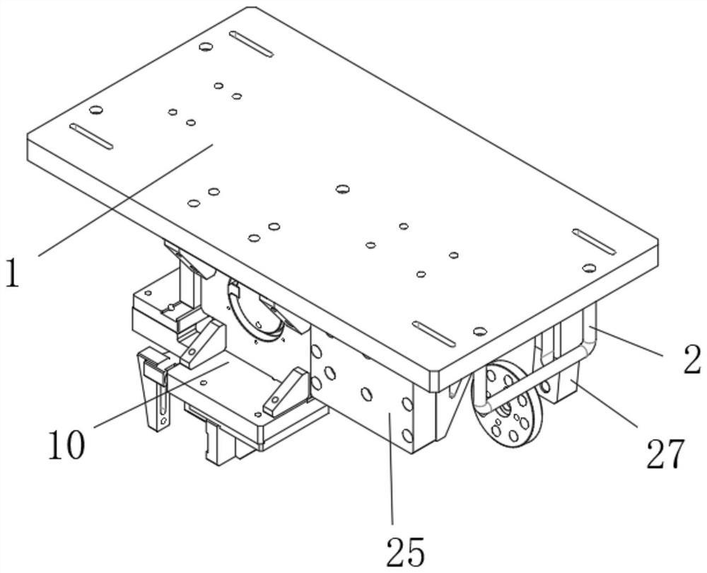
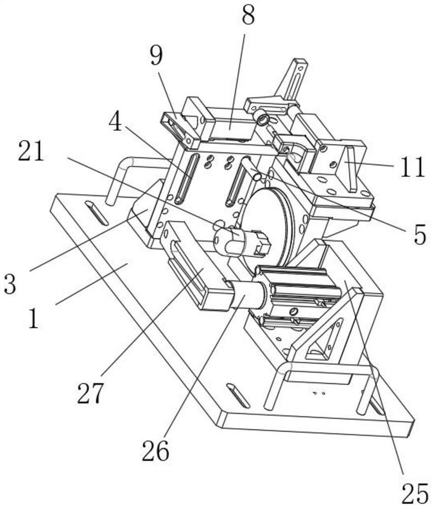
The automatic positioning marking clamp comprises a supporting plate and a sliding plate, hanging brackets are fixed to the tops of the left end and the right end of the supporting plate, a foot stool plate is arranged on the upper side of the left end of the supporting plate, a plate groove is formed in the end wall of the foot stool plate, a connecting cylinder is arranged at the inner side end of the plate groove in a penetrating mode, and the sliding plate is arranged at the upper end of the foot stool plate. A sliding groove is formed in the bottom end wall of the sliding plate, an air cylinder is installed at the upper end of the sliding plate, an air cylinder swing arm is arranged at the end of the air cylinder, and a supporting seat is installed at the right side end of the sliding plate. The automatic positioning and marking clamp has the beneficial effects that the automatic positioning and marking clamp can be conveniently clamped with the top end of a foot stand plate through the sliding groove in the bottom end of the sliding plate, assembling and disassembling of the foot stand plate are convenient, the air cylinder assembled to the top of the sliding plate through screws can be assembled and controlled accordingly, cleaning and maintenance are convenient, meanwhile, the air cylinder operates to drive the air cylinder swing arm to operate, and the working efficiency is improved. And the end part of the workpiece arranged on the supporting plate can be limited and positioned by utilizing the movement of the swing arm of the air cylinder.

Description

technical field [0001] The invention relates to the technical field of marking fixtures, in particular to an automatic positioning marking fixture. Background technique [0002] Marking In production, according to regulations or self-management needs, mark text, pictures, etc. on the product, such as: production date, expiration date, product number, etc. This process is called marking, and marking fixtures are often used when marking finished workpieces. [0003] The existing marking fixtures cannot conveniently place and assemble the workpieces during use, and at the same time the workpieces cannot be fixed stably. As a result, information such as two-dimensional codes is prone to deviation during marking, which cannot meet the processing needs. , and the structure of each part of the clamp body cannot be flexibly coordinated, resulting in inflexibility in use, poor practical performance, and inability to adapt and position special bent tube-shaped objects, resulting in p...

Claims


Application Information

Patent Timeline
Patent Type & Authority Applications(China)
IPC IPC(8): B41J3/407
CPCB41J3/40731B41J3/4073
Inventor 蔡金雨
Owner 无锡市蠡湖铸业有限公司
Why Eureka
Try Eureka