A kind of downhole intelligent water distributor
A water distributor, intelligent technology, applied in the direction of wellbore/well components, machines/engines, mining fluids, etc., can solve the problems of difficult to push communication cables, damage the stability of the electronic control system, etc., and achieve easy, fast and controllable Effect
- Summary
- Abstract
- Description
- Claims
- Application Information
AI Technical Summary
Problems solved by technology
Method used
Image
Examples
Embodiment 1
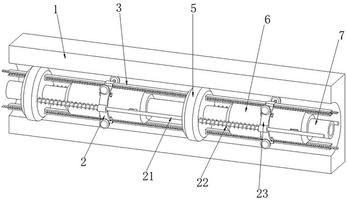
[0025] Example 1: see Figure 1-2 As shown, an intelligent downhole water distributor includes a water injection well 1, a packer 5, a water distributor 6 and a water injection pipeline 7. The water injection well 1 is internally connected with a number of evenly distributed packers 5, and the middle position of the packer 5 A water injection pipe 7 is connected to the water injection pipe 7, and a water distributor 6 is connected to the side of the outer side wall of the water injection pipe 7 close to the packer 5; The distances are equal in size, the packer 5 is in close contact with the inner wall of the water injection well 1, and a water distributor 6 is connected to the outside of the water injection pipe 7 at intervals of the same distance, and the water distributors 6 are connected to each other through communication cables and data communication transmission ; One side of the outer side wall of the packer 5 is provided with a support mechanism 2, the support mechanis...
Embodiment 2
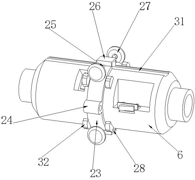
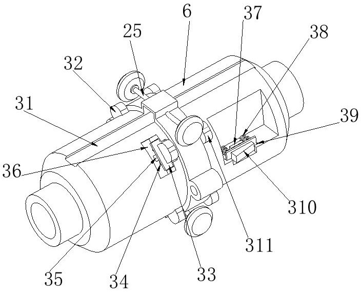
[0026] Example 2: see Figure 3-8 As shown, the upper surface of the water distributor 6 is provided with a moving mechanism 3, and the moving mechanism 3 includes an installation groove 31. The upper and lower surfaces of the water distributor 6 are connected with a sliding cavity 312 at the position corresponding to the installation groove 31, and the outer side wall of the water distributor 6 is provided with an elastic Cavity 39, a third spring 38 is connected on both sides of the inner rear surface of the elastic cavity 39, one end of the third spring 38 is connected to the inner rear surface of the elastic cavity 39, and the other end is connected to the limit plate 33 on the extrusion block 310, The front end of the third spring 38 is connected with a pressing block 310, and a second pressure sensor 37 is connected at the middle position of the inner rear surface of the elastic cavity 39. The second pressure sensor 37 can detect the pressure on the pressing block 310, an...
Embodiment 3
[0027] Example 3: see Figure 9-10As shown, a power supply mechanism 4 is provided at the position of the outer side wall of the water distributor 6 corresponding to the sliding cavity 312, and the power supply mechanism 4 includes a linkage cavity 42. The outer side wall of the sliding cavity 312 corresponds to the position of the linkage cavity 42. The gear 43, the inner side wall of the sliding cavity 312 is connected with a fourth gear column through the rotation shaft at the position corresponding to the second gear 43, and the second gear 43 is mutually embedded with the tooth slot on the drag plate 314 through the fourth gear column on the coaxial The inner side wall of the interlocking cavity 42 is connected with the first gear 41 at the position corresponding to the second gear 43, and the water distributor 6 is provided with a power generation cavity 46 at the position close to the first gear 41, and the inner lower surface of the power generation cavity 46 correspond...
PUM
 Abstract
Description
Claims
Application Information
 - R&D
- Intellectual Property
- Life Sciences
- Materials
- Tech Scout
- Unparalleled Data Quality
- Higher Quality Content
- 60% Fewer Hallucinations
Browse by: Latest US Patents, China's latest patents, Technical Efficacy Thesaurus, Application Domain, Technology Topic, Popular Technical Reports.
© 2025 PatSnap. All rights reserved.Legal|Privacy policy|Modern Slavery Act Transparency Statement|Sitemap|About US| Contact US: help@patsnap.com


