Optical fiber pitch conversion tool, optical connector, pitch conversion line, optical conversion box, and optical fiber pitch conversion method
A technology for changing lines and spacing, applied to the coupling of optical waveguides, instruments, light guides, etc., can solve problems such as cumbersome operations
- Summary
- Abstract
- Description
- Claims
- Application Information
AI Technical Summary
Problems solved by technology
Method used
Image

Examples
no. 1 approach >
[0034] refer to Figure 1 to Figure 8 , the first embodiment of the present invention will be described.
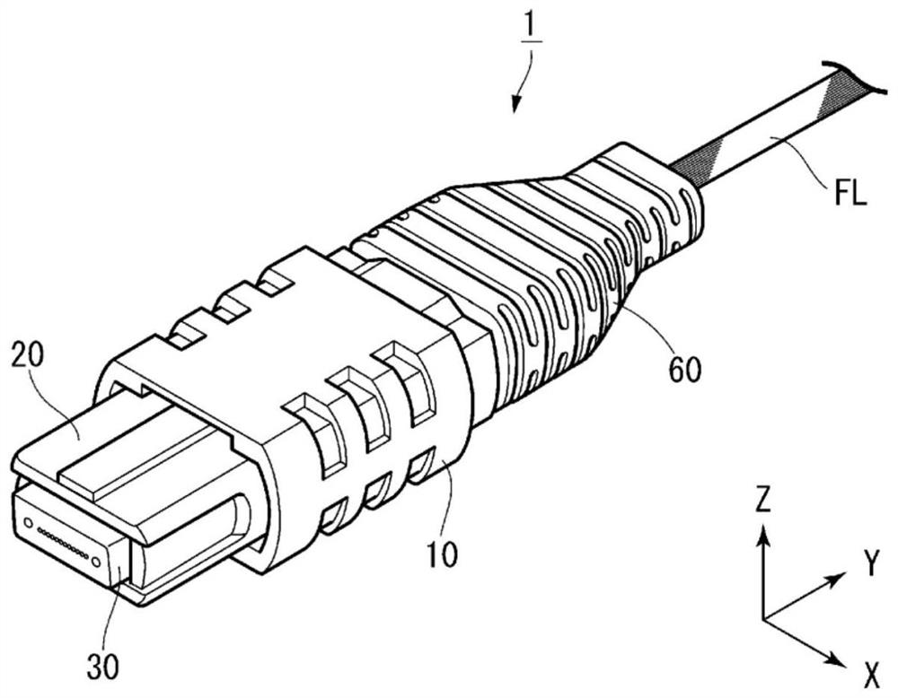
[0035] figure 1 It is a perspective view showing the optical connector 1 according to this embodiment. The optical connector 1 includes an optical fiber pitch conversion tool (hereinafter, simply referred to as "tool") according to this embodiment.
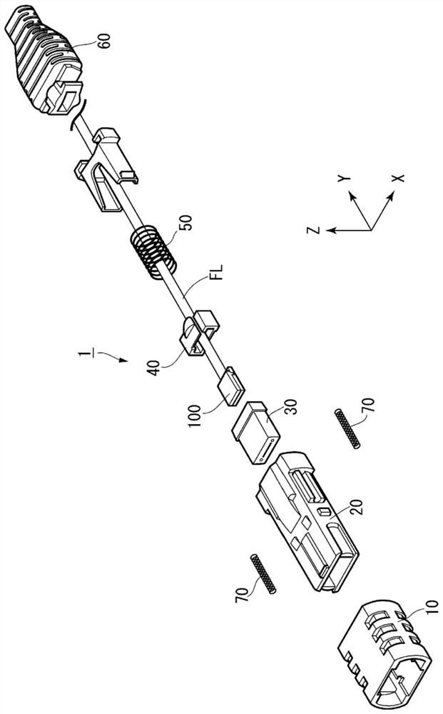
[0036] figure 2 It is an exploded view showing the optical connector 1 . The optical connector 1 is an MT (Mechanically Transferrable) multi-core connector, also called an MPO (Multi-fiber Push-On) connector. Since its basic structure is well known, the well-known structure will be briefly described.
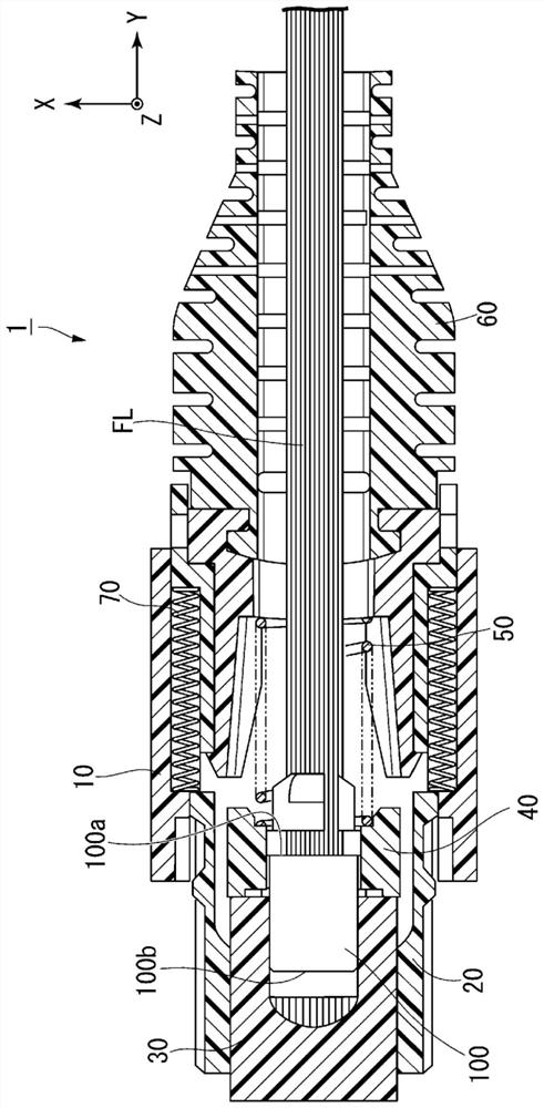
[0037] The optical connector 1 includes a puller member 10 , a case 20 , a ferrule 30 , a pin clamp 40 , a first spring 50 , a support portion 60 , two second springs 70 , and a tool 100 . The ferrule 30 , the pin clamp 40 and the first spring 50 are arranged inside the housing 20 . The pulling member 10 and the second ...
no. 2 approach >
[0074] refer to Figure 9 to Figure 12 A second embodiment of the present invention will be described. In the following description, the same reference numerals are assigned to the same configurations as those already described, and overlapping descriptions will be omitted.
[0075] Figure 9 It is a perspective view showing the optical connector 201 of this embodiment. The optical connector 201 is a fusion splice connector used for attaching an optical fiber ribbon FL prepared by a user. The basic structure of the fusion connector is well known, so a part of the description of the known structure will be omitted.
[0076] Figure 10 is a cross-sectional view of the optical connector 201 . The fused fibers Fm fused with the optical fibers prepared by the user are arranged neatly at the first pitch P1. One end (ferrule-side end) of the fused fiber is inserted into the first end 150a of the fiber pitch conversion tool 150, and the alignment pitch is converted to the second...
no. 3 approach >
[0089] refer to Figure 13 to Figure 15 , the third embodiment of the present invention will be described. In this embodiment, a pitch conversion cable using an optical fiber pitch conversion tool and the like will be described.
[0090] exist Figure 13 A schematic diagram of the pitch conversion line 301 according to this embodiment is shown in . The pitch conversion wire 301 includes: a wire body 302 ; and a first pitch end 303 and a second pitch end 304 arranged at both ends of the wire body 302 .
[0091] Inside the wire main body 302, a plurality of optical fibers f pass through. The first pitch end 303 has a first ferrule 303a having a plurality of insertion holes arranged at a first pitch P1, and is configured to be connectable to another optical connector or the like. The second pitch end 304 has a second ferrule 304a having a plurality of insertion holes arranged at a second pitch P2, and is configured to be connectable to another optical connector or the like. ...
PUM
 Abstract
Description
Claims
Application Information
 - R&D
- Intellectual Property
- Life Sciences
- Materials
- Tech Scout
- Unparalleled Data Quality
- Higher Quality Content
- 60% Fewer Hallucinations
Browse by: Latest US Patents, China's latest patents, Technical Efficacy Thesaurus, Application Domain, Technology Topic, Popular Technical Reports.
© 2025 PatSnap. All rights reserved.Legal|Privacy policy|Modern Slavery Act Transparency Statement|Sitemap|About US| Contact US: help@patsnap.com