Rainwater recycling and irrigating equipment for building

A technology for construction and rainwater, which is applied in construction, drinking water installations, and general water supply conservation, etc. It can solve the problems of low irrigation efficiency and diffuse irrigation of rainwater that cannot be collected, and achieve the effect of increasing the scope

Active Publication Date: 2022-04-26
深圳市群安达建筑科技有限公司
View PDF13 Cites 0 Cited by
  • Summary
  • Abstract
  • Description
  • Claims
  • Application Information

AI Technical Summary

Problems solved by technology

[0005] In order to overcome the shortcomings of the above-mentioned patents that cannot diffuse and irrigate the collected rainwater, and can only irrigate small-area building construction, and the irrigation efficiency is low, the technical problem to be solved is: to provide a method that can diffuse and irrigate the collected rainwater Rainwater recovery irrigation equipment for buildings

Method used


Image

  • Rainwater recycling and irrigating equipment for building
  • Rainwater recycling and irrigating equipment for building
  • Rainwater recycling and irrigating equipment for building

Examples


Embodiment 1

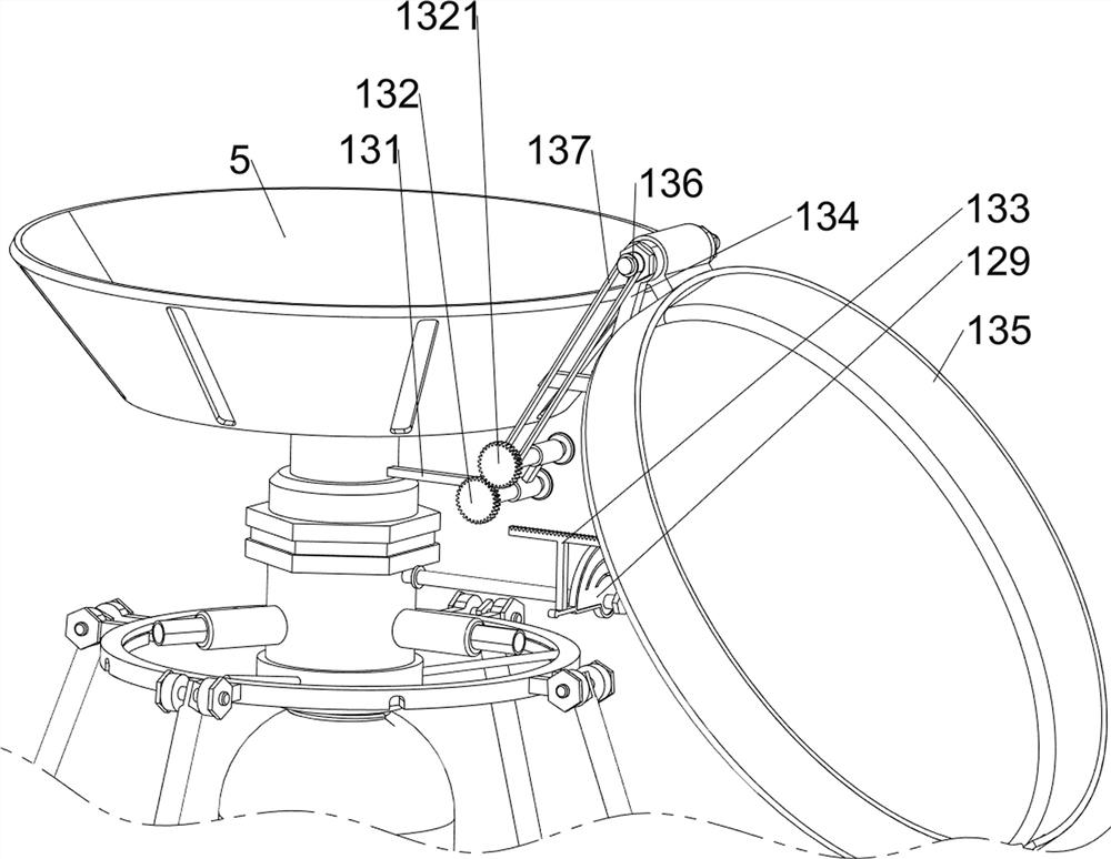
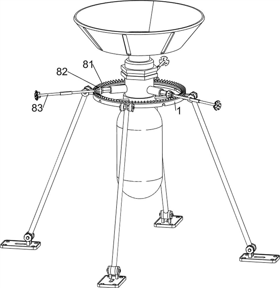
[0082] A rainwater recovery irrigation equipment for buildings, such as Figure 1-Figure 5 As shown, it includes a connecting frame 1, a first rotating rod 2, a first connecting plate 3, a fixed sleeve 4, a fixed frame 5, a first rotating frame 6, a water outlet pipe 61, a water tank 7, a diffusion mechanism 8 and a rotating mechanism 9 , the left and right sides and the front and rear sides of the outside of the connecting frame 1 are rotatably provided with first rotating rods 2, and the bottoms of the four first rotating rods 2 are provided with first connecting plates 3, which are used to support the device , the inside of the connecting frame 1 is provided with a fixed sleeve 4, and the top of the fixed sleeve 4 is rotatably provided with a first rotating frame 6, and the outer side of the first rotating frame 6 is provided with three outlet pipes 61 evenly spaced for spraying rainwater, thereby protecting the building. Construction is carried out watering, and first rota...

Embodiment 2

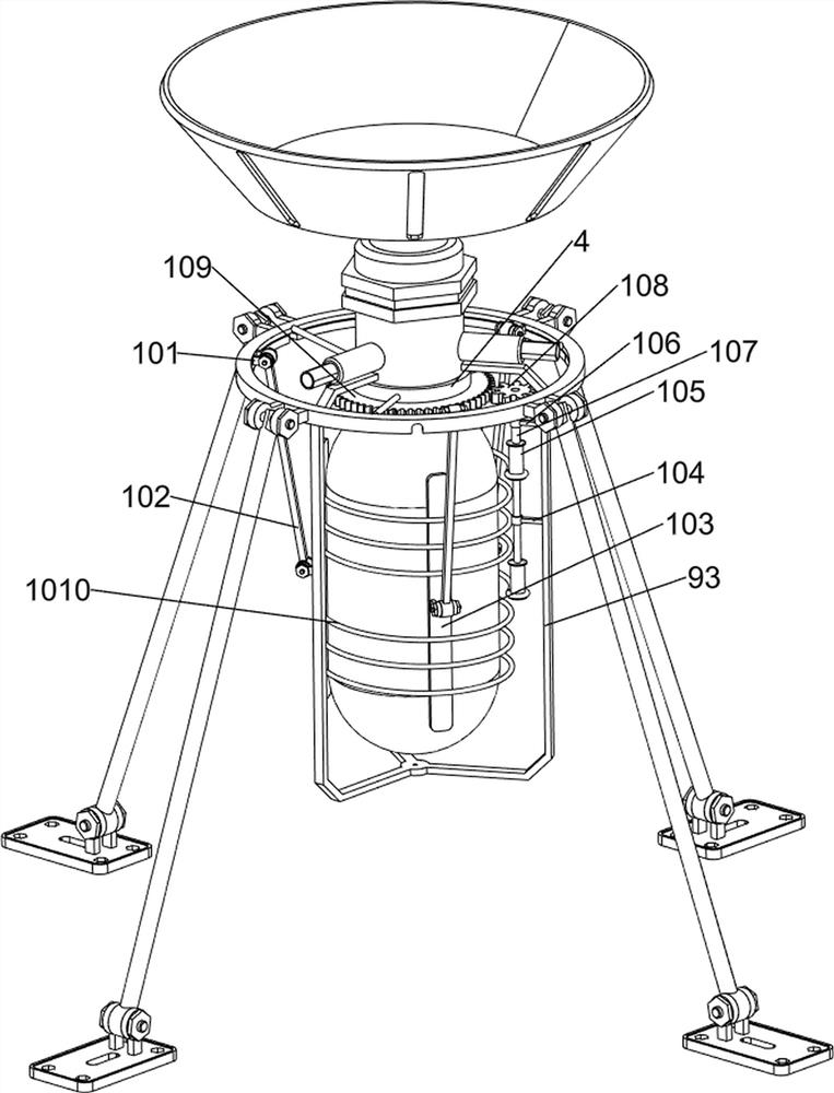
[0087] On the basis of Example 1, such as figure 1 with Image 6 As shown, an extrusion mechanism 10 is also included, and the extrusion mechanism 10 includes a support block 101, a rotating plate 102, a second connecting plate 103, a first fixed block 104, a first reel 105, a second fixed block 106, The second rotating rod 107, the first full gear 108, the second full gear 109 and the first stay cord 1010, three support blocks 101 are evenly spaced inside the connecting frame 1, and a rotating plate is provided on the three support blocks 101 102, the inner sides of the lower parts of the three rotating plates 102 are all rotatably provided with a second connecting plate 103, and the three second connecting plates 103 are all in contact with the water tank 7, and the middle part of the left side of the connecting frame 93 is provided with a first fixed block 104, On a fixed block 104, the rotation type is provided with the first reel 105, and the upper part of the left side ...


PUM


Abstract

The invention relates to irrigation equipment, in particular to rainwater recycling and irrigation equipment for buildings. The rainwater recycling and irrigating equipment for the building can be used for diffusing and irrigating collected rainwater. According to the rainwater recycling and irrigating equipment for the building, first rotating rods are rotationally arranged on the left side, the right side, the front side and the rear side of the outer side of a connecting frame; the first connecting plates are arranged at the bottoms of the four first rotating rods; the fixing sleeve is arranged in the connecting frame; the first rotating frame is rotationally arranged at the top of the fixing sleeve; the three water outlet pipes are evenly arranged on the outer side of the first rotating frame at intervals. The spur gear rotates to be in contact with the gear ring, so that the spur gear drives the rotating spray head to rotate, the rotating spray head rotates to diffuse and spray rainwater, and the rainwater irrigation range is enlarged.

Description

technical field [0001] The invention relates to an irrigation device, in particular to a rainwater recycling irrigation device for buildings. Background technique [0002] Water resources are an important part of natural resources. With the rapid development of society, people's demand for water is increasing. There are many regions and countries that lack water. Rainwater collection and waste water recycling are the actual use of water resources. status quo. [0003] Patent application CN212866267U, with a publication date of 20210402, discloses a rainwater recycling device for construction, including a water collection tank, the top of the water collection tank is connected with a water collection pipe, and water outlet holes are provided on both sides of the bottom of the water collection tank. A one-way valve is installed in the hole, a filter screen is provided in the water collection tank, and an L-shaped clamping plate is installed on the connection of the filter scr...

Claims


Application Information

Patent Timeline
Patent Type & Authority Applications(China)
IPC IPC(8): A01G25/02E03B3/02B05B15/68B05B3/02
CPCA01G25/02E03B3/02B05B15/68B05B3/02Y02A20/108
Inventor 李翠双
Owner 深圳市群安达建筑科技有限公司
Why Eureka
Try Eureka