Clamp for plane milling of upper template of stamping die

A stamping die and plane milling technology, which is applied in the field of mold processing fixtures, can solve the problems of scattered debris falling on the ground, inconvenient use, inconvenient cleaning, etc., and achieve the effect of easy operation, convenient use, and easy cleaning

Inactive Publication Date: 2022-04-26
芜湖元正模具机械有限公司
View PDF0 Cites 0 Cited by
  • Summary
  • Abstract
  • Description
  • Claims
  • Application Information

AI Technical Summary

Problems solved by technology

[0003] The existing fixtures have certain disadvantages when used. The existing fixtures fix the workpiece by bolts. The corresponding size needs to be customized to fix the workpiece, which is inconvenient to use, and the workpiece is easy to produce during processing. A lot of debris is scattered and falls on the ground, which is not easy to clean up

Method used


Image

  • Clamp for plane milling of upper template of stamping die
  • Clamp for plane milling of upper template of stamping die
  • Clamp for plane milling of upper template of stamping die

Examples


Embodiment Construction

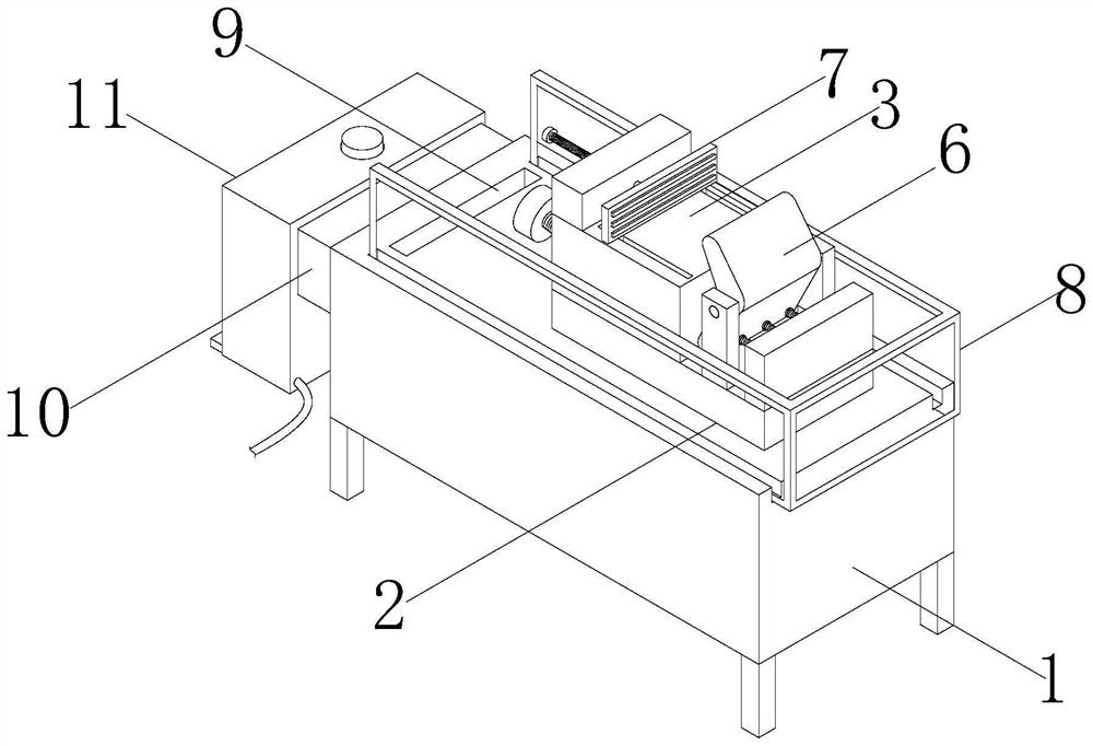
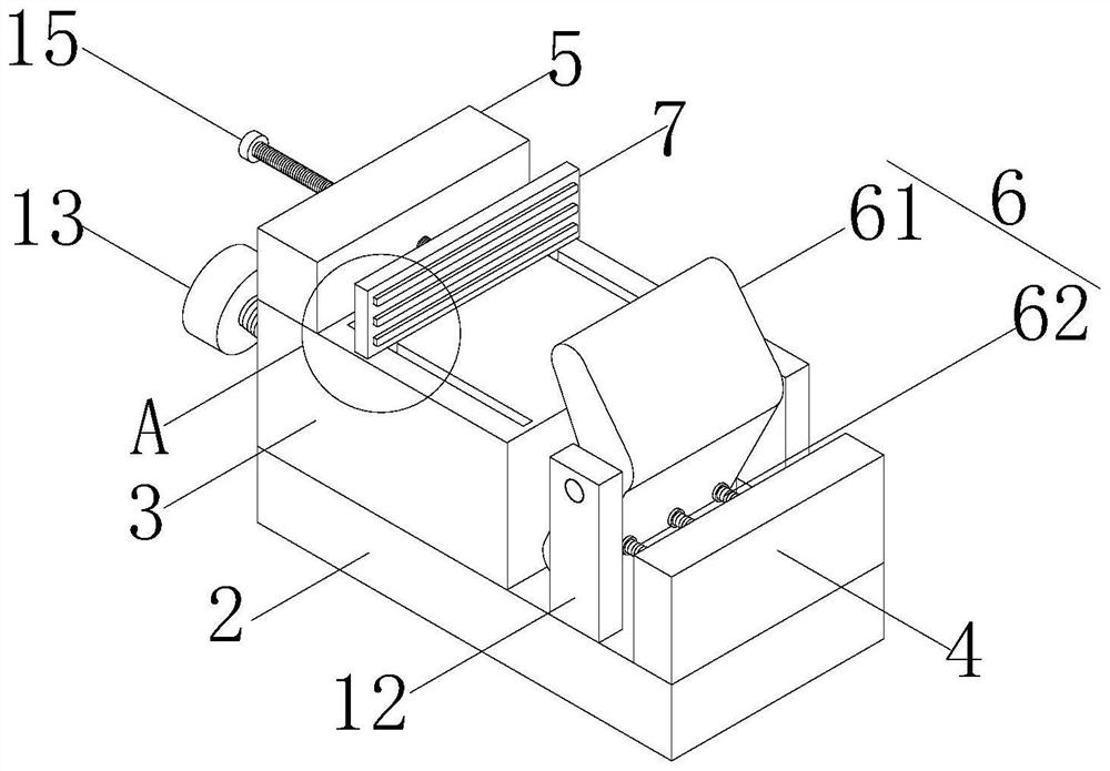
[0022] refer to Figure 1-Figure 5 , the present invention proposes a fixture for template milling on a stamping die, including a clamping seat 1, a fixing seat 2 is installed on the clamping seat 1, a card seat 3 and a first fixing block 4 are installed on the fixing seat 2, and on the card seat 3 A second fixed block 5 is installed, and a locking piece 6 for workpiece clamping is installed on the fixed seat 2, and the locking piece 6 is located between the deck 3 and the first fixed block 4, and a limit block is installed on the second fixed block 5 7 and a driving member for driving the limit block 7 to approach or move away from the locking member 6. A chute is provided on the deck 3, a slide block 14 slidably connected with the chute is installed on the limit block 7, and the driver includes a second threaded rod 15 threaded on the second fixed block 5, and the second thread One end of the rod 15 is rotatably connected to the limiting block 7 , and the end of the second ...


PUM


Abstract

The clamp for plane milling of the upper die plate of the stamping die comprises a clamping base, a fixing base is installed on the clamping base, a clamping base and a first fixing block are installed on the fixing base, a second fixing block is installed on the clamping base, and a locking piece used for clamping a workpiece is installed on the fixing base. The locking piece is located between the clamping base and the first fixing block, and the second fixing block is provided with a limiting block and a driving piece used for driving the limiting block to be close to or away from the locking piece; a protective cover is slidably connected to the clamping base, the fixing base is located in the protective cover, a scrap opening is formed in the clamping base, a dust suction part communicating with the scrap opening is installed on the side face of the clamping base, and a cleaning part is installed on the side, away from the clamping base, of the dust suction part. According to the clamp for plane milling of the upper die plate of the stamping die, the problem that upper die plates of different sizes are inconvenient to fix is solved, and sweeps generated during plane milling of the upper die plate are also convenient to clean.

Description

technical field [0001] The invention relates to the technical field of clamps for mold processing, in particular to a clamp for milling planes of templates on stamping dies. Background technique [0002] Stamping die is a special process equipment for processing materials into parts in cold stamping processing. Or plastic deformation, so as to obtain a pressure processing method for the required parts. The stamping die is composed of an upper die and a lower die. When processing the upper die of the stamping die, it needs to be milled and plane-milled. During processing, it is necessary to use a fixture to It clamps. [0003] The existing fixtures have certain disadvantages when used. The existing fixtures fix the workpiece by bolts. The corresponding size needs to be customized to fix the workpiece, which is inconvenient to use, and the workpiece is easy to produce during processing. More waste debris is scattered and falls on the ground, which is not convenient for clean...

Claims


Application Information

Patent Timeline
IPC IPC(8): B23Q3/06B23Q11/00B23Q11/08
CPCB23Q3/06B23Q11/0046B23Q11/0042B23Q11/08
Inventor 夏必龙
Owner 芜湖元正模具机械有限公司
Why Eureka
Try Eureka