Shearing equipment for pasting film on electronic equipment

A technology of electronic equipment and shearing equipment, which is applied in metal processing and other directions, can solve the problems of poor shearing effect, different sizes of electronic equipment, increasing the pressure of L-shaped bearing plate and electronic equipment shell, etc., and achieves controllable fixing force , to ensure the effect of accuracy

Inactive Publication Date: 2022-04-26
江西宏均光电有限公司
View PDF1 Cites 0 Cited by
  • Summary
  • Abstract
  • Description
  • Claims
  • Application Information

AI Technical Summary

Problems solved by technology

[0003] For example, the Chinese patent discloses: a kind of high-efficiency shearing device for electronic equipment casing film, publication number: CN111941818A, it is by being provided with L-shaped bearing plate, slide rail, fixed plate and limit corner block, has avoided cutting process The middle shearing wheel touches the electronic equipment, thereby causing slight damage to the electronic equipment and improving the safety of the shearing of the overall device. By setting the first motor, the rotating shaft, the threaded rod, the sliding rod, the sliding block, the sliding sleeve, The connecting plate, the second motor and the shearing wheel promote the movement of the shearing wheel on the prescribed track after the electronic equipment casing is pasted on the film, which improves the shearing efficiency of the overall device. There are extrusion protrusions distributed equidistantly, which increases the pressure between the L-shaped bearing plate and the electronic equipment casing, thereby promoting the stability of the electronic equipment casing, preventing the problem of lateral deviation of the electronic equipment casing and by setting a fixed The cylinder, the fixed shaft, the spring and the welding sheet promote the extrusion of the two L-shaped bearing plates to the opposite side, which plays a role in fixing the electronic equipment casing. At the same time, the anti-tilt ring is provided to effectively prevent the fixed shaft from tilting. The role of the device, thus strengthening the fixing effect of the electronic device shell, but when the device is in use, the shearing wheel can only move on the specified track, it is difficult to adjust the position of the shearing wheel, but the size of the electronic device is different, so the device Difficult to cut for different sizes of film, the cutting effect is poor

Method used


Image

  • Shearing equipment for pasting film on electronic equipment
  • Shearing equipment for pasting film on electronic equipment
  • Shearing equipment for pasting film on electronic equipment

Examples


Embodiment Construction

[0030] In order to make the objectives, technical solutions and advantages of the present application clearer, the technical solutions of the present application will be clearly and completely described below with reference to the specific embodiments of the present application and the corresponding drawings. Obviously, the described embodiments are only a part of the embodiments of the present application, but not all of the embodiments. Based on the embodiments in the present application, all other embodiments obtained by those of ordinary skill in the art without creative efforts shall fall within the protection scope of the present application.

[0031] The technical solutions provided by the embodiments of the present application will be described in detail below with reference to the accompanying drawings.

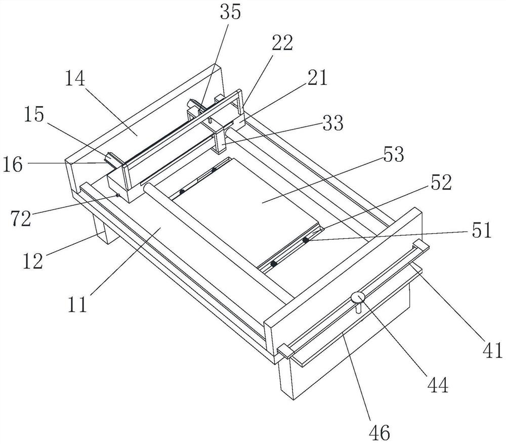
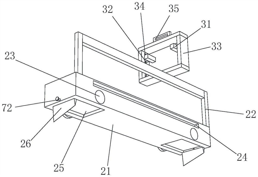
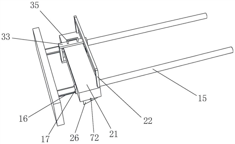
[0032] see figure 1 , figure 2 , image 3 , Figure 4 , Figure 5 , Image 6 and Figure 7 , a shearing device for filming electronic equipment, comprising a...


PUM


Abstract

The invention relates to the technical field of electronic equipment film pasting, in particular to shearing equipment for electronic equipment film pasting, which comprises a workbench, supporting plates symmetrically and fixedly mounted at the lower end part of the workbench, a placing groove formed in the middle of the upper end part of the workbench, side plates symmetrically and fixedly mounted at the upper end part of the workbench, and sliding columns symmetrically and fixedly mounted between the two side plates, connecting columns are symmetrically and fixedly installed on the side wall of the side plate located at the left end, fixing discs are fixedly installed at the ends, away from the side plates, of the two connecting columns, the surfaces of the two sliding columns are movably sleeved with a shearing mechanism, the shearing mechanism comprises a sliding block, a first pull rod is fixedly installed at the upper end of the sliding block, and circular grooves are symmetrically formed in the side wall of the sliding block in a penetrating mode; and the two sliding columns are movably arranged in the circular grooves, clamping grooves are symmetrically formed in the side walls of the sliding blocks, and moving grooves are symmetrically formed in the lower end portions of the sliding blocks, so that when the equipment is used, pasting films of different sizes can be cut according to production requirements, and the film pasting requirements of equipment of different sizes can be met.

Description

technical field [0001] The present application relates to the technical field of film sticking of electronic equipment, and in particular, to a cutting device for sticking film of electronic equipment. Background technique [0002] Electronic equipment, basically explained as electrical equipment composed of microelectronic devices. Electronic equipment refers to equipment that is composed of electronic components such as integrated circuits, transistors, and electronic tubes, and uses electronic technology (including) software to play a role, including electronic computers and robots, numerical control or program-controlled systems controlled by electronic computers. Electronic equipment film refers to the installation of a thin layer of glass film or PP, PVC material and other products on the surface of the electronic equipment display screen. [0003] For example, a Chinese patent discloses: a high-efficiency shearing device for filming an electronic equipment shell, pub...

Claims


Application Information

Patent Timeline
Patent Type & Authority Applications(China)
IPC IPC(8): B26D1/11B26D7/00B26D7/26
CPCB26D1/115B26D7/2628B26D7/00
Inventor 石生秀
Owner 江西宏均光电有限公司
Why Eureka
Try Eureka