Novel underbeam-free lift car structure
A car, a new type of technology, applied in mechanical equipment, springs/shock absorbers, elevators in buildings, etc., can solve problems such as increased temperature of straight beams and guide rails, weak support at the bottom of the car, inconvenient lubrication and cooling treatment, etc. , to achieve the effect of improving ride comfort and safety, avoiding looseness, and stabilizing support force
- Summary
- Abstract
- Description
- Claims
- Application Information
AI Technical Summary
Problems solved by technology
Method used
Image
Examples
Embodiment 1
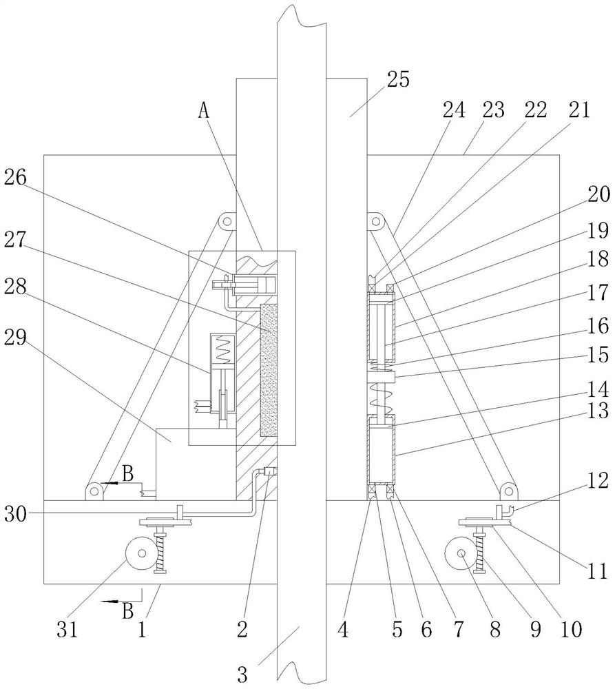
[0027] A new car structure without a lower beam, including a car floor 1, a car body 23 fixed on the car floor 1, and a straight beam 25. The straight beam 25 slides up and down on the guide rail 3, and both sides of the straight beam 25 pass through The reinforcing bar 24 is connected with the car bottom 1, and also includes:
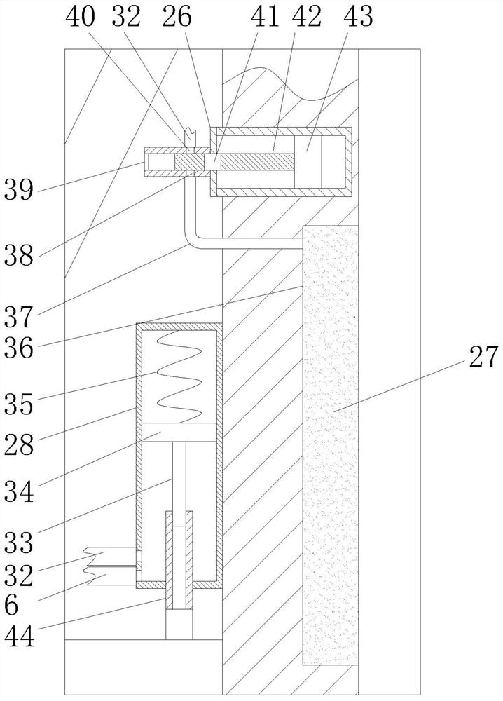
[0028] The vibration kinetic energy absorbing mechanism arranged on the straight beam 25 is used to absorb and transform the vibration energy generated by the entire car during operation;
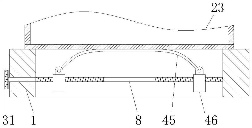
[0029] The buffer support mechanism is installed on the car bottom 1 and has the function of anti-loosening. The buffer support mechanism is used to buffer, shock absorb and support the bottom of the car body 23, and the vibration kinetic energy absorption mechanism is dynamically connected with the buffer support mechanism in a pneumatic manner. ;
[0030] An adaptive lubrication mechanism that is arranged on the straight beam 25 and prevents the wear and tear bet...
Embodiment 2
[0032] In this embodiment, the vibration kinetic energy absorbing mechanism includes a pump barrel 13 and a pump barrel 2 18 fixed on the straight beam 25, the pump barrel 13 and the pump barrel 2 18 are arranged oppositely, and the central axes are all arranged in parallel with the guide rail 3, the pump Cylinder one 13 and pump cylinder two 18 are respectively slidably connected to piston plate one 14 and piston plate two 19. Piston plate one 14 and piston plate two 19 are fixedly connected by a sliding rod 17, and the sliding rod 17 runs through and is slidably connected to the pump. On the opposite end wall of cylinder one 13 and pump cylinder two 18, a weight 15 is fixed in the middle of the slide bar 17, and the weight 15 is located between the pump cylinder one 13 and the pump cylinder two 18, and the weight 15 passes through the spring one 16 respectively. It is connected with pump barrel one 13 and pump barrel two 18.
[0033] In this embodiment, the buffer support me...
PUM
 Abstract
Description
Claims
Application Information
 - R&D
- Intellectual Property
- Life Sciences
- Materials
- Tech Scout
- Unparalleled Data Quality
- Higher Quality Content
- 60% Fewer Hallucinations
Browse by: Latest US Patents, China's latest patents, Technical Efficacy Thesaurus, Application Domain, Technology Topic, Popular Technical Reports.
© 2025 PatSnap. All rights reserved.Legal|Privacy policy|Modern Slavery Act Transparency Statement|Sitemap|About US| Contact US: help@patsnap.com


