Driving shaft, rotor and centrifugal machine thereof
A drive shaft and centrifuge technology, applied in the field of centrifuges, can solve the problems of low reliability, cumbersome and complicated operation, etc., and achieve the effects of simple and effective operation, avoiding safety accidents and reducing operation burden.
- Summary
- Abstract
- Description
- Claims
- Application Information
AI Technical Summary
Problems solved by technology
Method used
Image

Examples
Embodiment 1
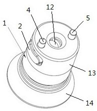
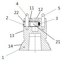
[0023] figure 1 It is a schematic diagram of the drive shaft provided by Embodiment 1 of the present invention. figure 2 It is a sectional view of the drive shaft provided by Embodiment 1 of the present invention. During the centrifugation operation, the test tube (not shown) containing the biological sample to be centrifuged is put into the rotor (not shown), and then the rotor is locked on the drive shaft, and the drive shaft rotates for centrifugation.
[0024] combine figure 1 with figure 2 , The drive shaft includes a drive shaft body 1 , a lock tongue 2 and a spring 3 . The outer surface of the drive shaft body 1 includes a cylindrical surface 13 and a truncated cone surface 14 . A first groove 11 is provided on the side surface and the cylindrical surface 13 of the drive shaft body 1 , and the locking tongue 2 and the spring 3 are accommodated in the first groove 11 . Both ends of the spring 3 are respectively connected with the inner wall of the drive shaft body...
Embodiment 2
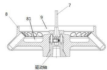
[0032] image 3 It is a sectional view of locking the rotor and the drive shaft provided by Embodiment 2 of the present invention. Figure 4 It is a partial cross-sectional view of the locking of the rotor and the drive shaft provided by Embodiment 2 of the present invention. Figure 5 It is a partial sectional view of the unlocking of the rotor and drive shaft provided by Embodiment 2 of the present invention. In the embodiment of the present invention, the components that are the same as those in the first embodiment use the same symbols as those in the first embodiment, including all the features described in the first embodiment, and will not be repeated here.
[0033] combine image 3 , Figure 4 with Figure 5 , the rotor includes a rotor body 8 and a rotor cover 9 , and the housing cavity 81 of the rotor body 8 is closed by the rotor cover 9 . The central shaft of the rotor is a hollow structure, and the inner wall thereof is provided with a second groove 6 . As d...
Embodiment 3
[0039] Image 6 It is a schematic diagram of the centrifuge provided by Embodiment 3 of the present invention. Such as Image 6 As shown, the centrifuge includes a motor, a centrifuge cavity, the rotor described in the second embodiment and the drive shaft described in the first embodiment.
[0040] In the embodiment of the present invention, the drive shaft passes through the bottom of the cavity of the centrifuge and is connected with the central shaft of the rotor to lock the rotor on the drive shaft, and the rotor is located in the cavity of the centrifuge. Then put the test tube (not shown) containing the biological sample to be centrifuged into the rotor, close the door cover of the centrifuge, so that the rotor is located in the sealed cavity of the centrifuge, and the motor drives the drive shaft to rotate for centrifugation.
[0041] In the embodiment of the present invention, a lock tongue is provided in the first groove of the drive shaft body, and the lock tongue...
PUM
 Abstract
Description
Claims
Application Information
 - R&D
- Intellectual Property
- Life Sciences
- Materials
- Tech Scout
- Unparalleled Data Quality
- Higher Quality Content
- 60% Fewer Hallucinations
Browse by: Latest US Patents, China's latest patents, Technical Efficacy Thesaurus, Application Domain, Technology Topic, Popular Technical Reports.
© 2025 PatSnap. All rights reserved.Legal|Privacy policy|Modern Slavery Act Transparency Statement|Sitemap|About US| Contact US: help@patsnap.com