Face recognition equipment with light interference resisting function

A face recognition device and anti-light technology, applied in the field of face recognition, can solve the problems of inconvenient anti-light interference, inconvenient self-adaptive angle adjustment, etc., achieve fast and efficient adjustment process, save power and material energy, and improve recognition efficiency effect

Inactive Publication Date: 2022-04-29
CHIZHOU VOCATIONAL & TECHN COLLEGE
View PDF0 Cites 0 Cited by
  • Summary
  • Abstract
  • Description
  • Claims
  • Application Information

AI Technical Summary

Problems solved by technology

[0005] The purpose of the present invention is to provide a face recognition device with anti-light interference function to solve the above-mentioned background technology. The existing face recognition dev

Method used


Image

  • Face recognition equipment with light interference resisting function
  • Face recognition equipment with light interference resisting function
  • Face recognition equipment with light interference resisting function

Examples


Example Embodiment

[0028] Example 1

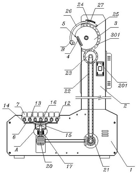
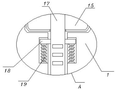
[0029] see Figure 1-4, including a base 1, a stand 2 is fixed on the top of the base 1, and a controller 201 is embedded in the stand 2, and a mounting ball 3 is embedded and movable on the top of the inner side of the stand 2 through a torsion spring, and the mounting ball 3 An identification camera 4 is fixed in the middle of the outside, and a fill light 5 is fixed at the edge position outside the mounting ball 3; a foot pedal 7, the foot pedal 7 is installed in the top groove 6 opened at the top of the base 1, and the foot pedal is The bottom of the protruding position of the 7 side is fixed with a positioning rod 8, and the positioning rod 8 is located in the positioning groove 9, the positioning groove 9 is opened on the top of the base 1, and a positioning spring is fixed between the positioning groove 9 and the bottom of the positioning rod 8 10. The top of the foot pedal 7 protrudes above the base 1, and the bottom of the foot pedal 7 is fixed wit...

Example Embodiment

[0030] Example 2

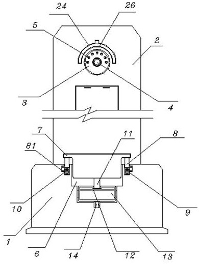
[0031] see figure 1 , image 3 and Figure 5-6 , the telescopic groove 24, the telescopic groove 24 is opened at the top of the inner side of the stand 2, and the bottom end of the telescopic groove 24 is fixed with an electromagnet 25, and a reflective protective plate 26 is movably installed in the telescopic groove 24, and the top of the reflective protective plate 26 A telescopic spring 27 is fixed between the protrusion and the inner wall of the telescopic groove 24. At the same time, one end of the reflective protective plate 26 is located outside the mounting ball 3. The front and side surfaces of the reflective protective plate 26 are designed in an arc structure. The end of the 26 is made of magnetic material to attract the electromagnet 25, and the reflective protection plate 26 is fitted and elastically slid in the expansion groove 24 through the expansion spring 27, and a concave lens 261 is fixed on the inner wall of the reflective protection ...


PUM


Abstract

The invention discloses face recognition equipment with a light interference resisting function, which comprises a base, a vertical frame is fixed at the top of the base, and a mounting ball is movably arranged at the top of the inner side of the vertical frame in an embedded manner through a torsional spring; the device further comprises a pedal plate, the pedal plate is installed in a top groove formed in the top of the base, the positioning groove is formed in the top of the base, the top of the pedal plate is located above the base in a protruding mode, the bottom of the first oil tank is connected with a second oil tank through an oil conveying pipe, and a second piston plate is installed in the second oil tank. A reset rod is fixed to the side of the rack, and one side of the rack is meshed with a tooth roller. And the telescopic groove is formed in the top of the inner side of the vertical frame. According to the face recognition equipment with the light interference resisting function, by sensing the treading positions of people of different heights, angle adjustment is achieved, the recognition camera is protected, light is shielded, meanwhile, internal light can be dispersed, and the light supplementing effect is improved.

Description

technical field [0001] The invention relates to the technical field of face recognition, in particular to a face recognition device with anti-light interference function. Background technique [0002] Face recognition is a biological technology that uses camera equipment to identify people based on facial features, and cooperates with the calculation of background programs to identify the corresponding personnel. It is often used in shopping malls, stations, companies and other places, but the existing face recognition equipment There are the following problems when using: [0003] The application of face recognition requires light source irradiation, but external strong light will affect the extraction of facial features by camera equipment. At the same time, the use of internal fill light is aimed at dark parts of the face, such as the nose area, which is blocked and leads to darker light. It will affect the recognition effect and increase the recognition time. The existi...

Claims


Application Information

Patent Timeline
IPC IPC(8): F16M11/04F16M11/10F16M11/18G06V40/16
CPCF16M11/043F16M11/10F16M11/18
Inventor 汪辉进刘红霞王家兰陈心怡胡石叶乔
Owner CHIZHOU VOCATIONAL & TECHN COLLEGE
Why Eureka
Try Eureka