Polarization measurement method, system and storage medium for improving array direction finding accuracy

A measurement method and direction finding technology, which are applied in radio wave measurement systems, direction-determining direction finder, direction finder using radio waves, etc. It is difficult to adapt to problems such as ultra-wideband polarization measurement, and achieve the effect of insensitive polarization purity, good real-time performance, and convenient implementation.

Active Publication Date: 2022-06-24
SOUTHWEST CHINA RES INST OF ELECTRONICS EQUIP
View PDF7 Cites 0 Cited by
  • Summary
  • Abstract
  • Description
  • Claims
  • Application Information

AI Technical Summary

Problems solved by technology

[0005] In engineering, the implementation of polarization measurement through orthogonally polarized antennas is limited by many factors, such as the requirement that the phase centers of the two antennas coincide, the high polarization purity requirements of the antenna itself, the difficulty of adapting to ultra-wideband polarization measurement, and the possibility of being easily affected by the electromagnetic environment of the surrounding installation platform. reflection effects etc.

Method used


Image

  • Polarization measurement method, system and storage medium for improving array direction finding accuracy
  • Polarization measurement method, system and storage medium for improving array direction finding accuracy
  • Polarization measurement method, system and storage medium for improving array direction finding accuracy

Examples


Embodiment 1

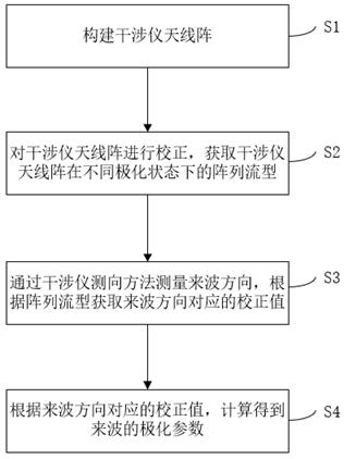
[0040] see figure 1 , the present invention provides an embodiment of a polarization measurement method for improving array direction finding accuracy, the method comprising the following steps:

[0041] S1. Build an interferometer antenna array;

[0042] S2. Correct the interferometer antenna array to obtain the array flow patterns of the interferometer antenna array in different polarization states;

[0043] Specifically, calibrating the interferometer antenna array includes performing horizontal and vertical polarization corrections or other orthogonal polarization corrections on the interferometer antenna array. Wherein, other orthogonal polarizations can be left-right circular polarization or ±45 degree oblique polarization.

[0044] Specifically, the array flow pattern is the horizontally polarized wave and the vertically polarized wave or other orthogonally polarized waves respectively received by each array element unit in the interferometer antenna array at the corr...

Embodiment 2

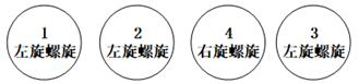
[0085] The following description will be given in conjunction with an implementation example of a 4-element antenna array.

[0086] see figure 2 , the antenna array includes three left-handed circularly polarized helical antennas and one right-handed circularly polarized helical antenna, among which three left-handed circularly polarized helical antennas constitute a traditional 3-element single-polarized interferometer antenna array. On the basis of the 3-element single-polarization interferometer antenna array, a right-handed circularly polarized helical antenna is added.

[0087] Perform horizontal and vertical polarization correction on the interferometer antenna array in an anechoic chamber, and obtain the array flow pattern in the horizontal and vertical polarization states of the array and . The corrected angle range is consistent with the direction finding field of view range, the corrected frequency band is consistent with the required measurement frequency band...

Embodiment 3

[0093] see Figure 4 , the present invention also provides an embodiment of the polarization measurement system for improving the direction finding accuracy of the array, including:

[0094] a building module 101 for building an interferometer antenna array;

[0095] an acquisition module 102, configured to calibrate the interferometer antenna array and acquire the array flow patterns of the interferometer antenna array in different polarization states;

[0096] The correction module 103 is used to measure the direction of the incoming wave by the interferometer direction finding method, and obtain the correction value corresponding to the direction of the incoming wave according to the array flow pattern;

[0097] The calculation module 104 is configured to calculate the horizontal polarization component and the vertical polarization component through polarization decomposition according to the correction value corresponding to the incoming wave direction, so as to obtain th...


PUM


Abstract

The invention discloses a polarization measurement method, system and storage medium for improving the accuracy of array direction finding. The method includes: constructing an interferometer antenna array; correcting the interferometer antenna array, and obtaining the interferometer antenna The array flow pattern of the array in different polarization states; the direction of incoming wave is measured by interferometer direction finding method, and the correction value corresponding to the incoming wave direction is obtained according to the array flow pattern and the incoming wave direction; the correction value corresponding to the incoming wave direction is obtained according to the array flow pattern and the incoming wave direction , to calculate the polarization parameter of the incoming wave. The present invention does not require the two antenna units to be orthogonal and the phase centers coincide, and the antenna does not need to be rotated by 90°. It is not sensitive to the polarization purity of the antenna itself and the environment of the antenna array platform, and is suitable for polarization measurement of ultra-wideband and large field of view. Combining the correction value of the antenna array itself and the direction finding result of the incoming wave, it can conveniently and accurately measure the polarization characteristics of the incoming wave signal in real time.

Description

technical field [0001] The invention relates to the technical field of antenna engineering or array signal processing, in particular to a polarization measurement method, system and storage medium for improving the direction finding accuracy of an array. Background technique [0002] Information such as frequency, repetition frequency, pulse width, amplitude, direction of incoming wave, and polarization are important attributes of radar signals. Usually, frequency, repetition frequency, pulse width, and amplitude can be directly measured by a digital receiver. The direction of incoming wave is generally obtained by interference. The direction finding method of the interferometer can be measured, but the polarization information is not easy to measure. At the same time, the polarization is one of the important factors affecting the direction finding accuracy of the interferometer. [0003] The interferometer direction finding method is widely used in the field of electronic c...

Claims


Application Information

Patent Timeline
Patent Type & Authority Patents(China)
IPC IPC(8): G01S3/14G01S3/48
CPCG01S3/146G01S3/48
Inventor 朱全江王浩丞沈志博刘俊唐勇
Owner SOUTHWEST CHINA RES INST OF ELECTRONICS EQUIP
Why Eureka
Try Eureka