A UAV multi-stage visual precision landing method and device

A UAV, multi-stage technology, applied in 3D position/course control, vehicle position/route/height control, instruments, etc., can solve the problem of inability to achieve a large landing height, accurate landing, safe landing, UAV landing target Point detection and positioning failure, hidden dangers of safe landing and other problems, to achieve the effect of low cost, convenient operation and strong generalization ability

Active Publication Date: 2022-07-12
ZHEJIANG LAB
View PDF2 Cites 1 Cited by
  • Summary
  • Abstract
  • Description
  • Claims
  • Application Information

AI Technical Summary

Problems solved by technology

[0005] The purpose of the present invention is to provide a multi-stage visual precision landing method and device for unmanned aerial vehicles, which solves the problem of the target being too large or too small in the camera imaging of a single tag in the initial stage and the completion stage of the landing in the prior art, resulting in no The human-machine detection and positioning of the landing target point is invalid, and there is a phenomenon of blind landing in a certain altitude range, which brings great hidden dangers to safe landing
The existence of the problem of blind landing has further led to the problem that the existing active visual landing technology cannot achieve accurate and safe landing at a large landing height (> 30 meters)

Method used


Image

  • A UAV multi-stage visual precision landing method and device
  • A UAV multi-stage visual precision landing method and device
  • A UAV multi-stage visual precision landing method and device

Examples


Embodiment Construction

[0029] The following description of at least one exemplary embodiment is merely illustrative in nature and is in no way intended to limit the invention, its application, or uses. Based on the embodiments of the present invention, all other embodiments obtained by those of ordinary skill in the art without creative efforts shall fall within the protection scope of the present invention.

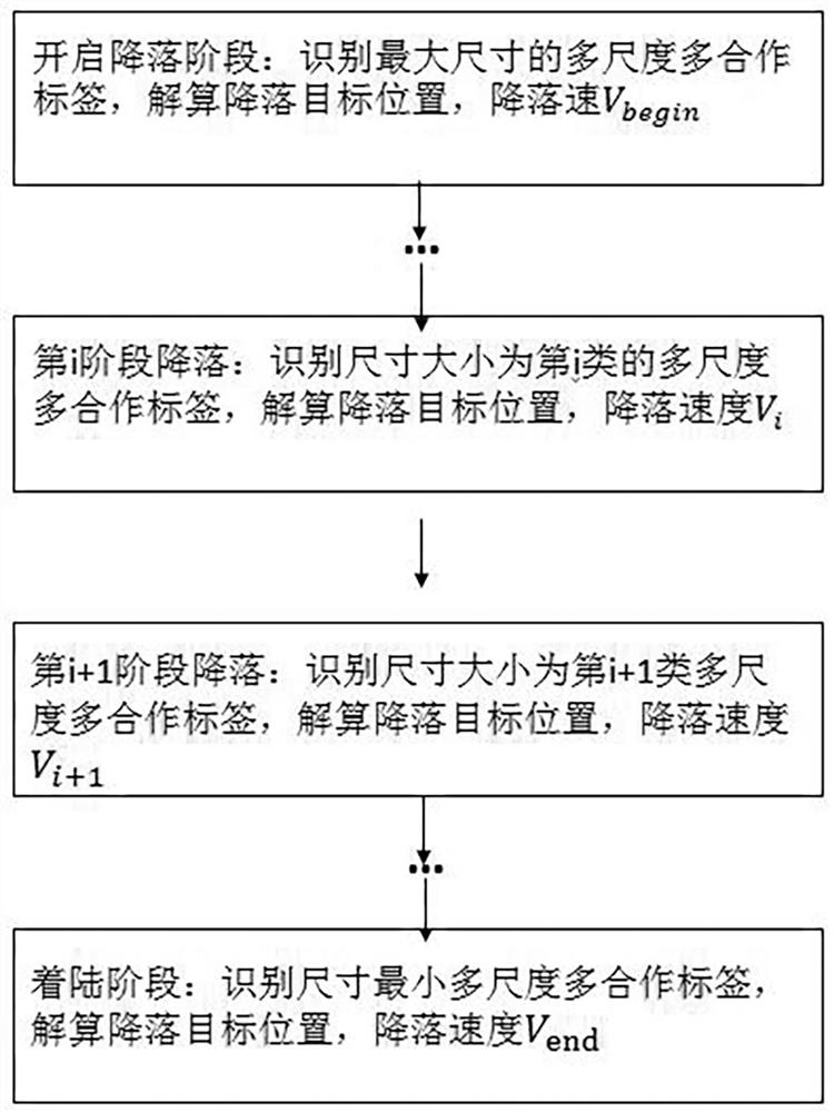
[0030] A multi-stage visual precision landing method for an unmanned aerial vehicle, comprising the following steps:

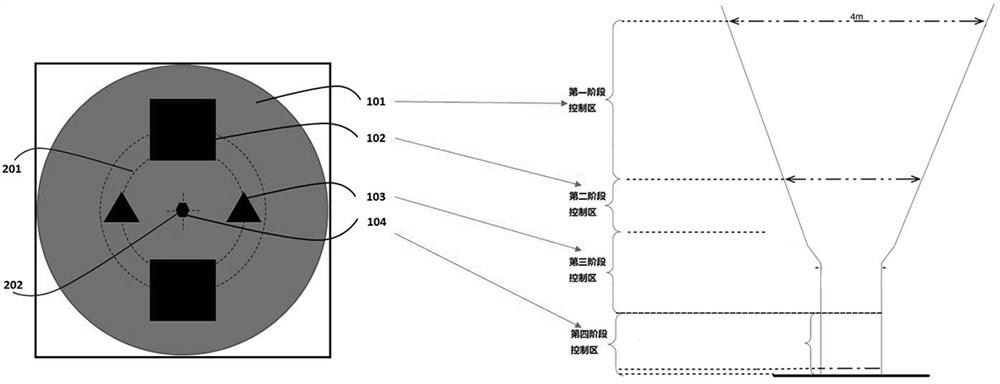
[0031] Step S1: Obtain the internal parameters of the airborne bird's-eye view camera and the actual landing height requirement of the UAV, and construct a ground visual landing sign with multi-scale and multi-cooperative labels;

[0032] The multi-scale multi-cooperation tags include multi-scale tags and multi-cooperation tags, the multi-cooperation tags are tags with different shapes, and each type of the multi-cooperation tags corresponds to a landing stage; the multi-scale...


PUM


Abstract

The invention discloses a multi-stage visual precision landing method for an unmanned aerial vehicle, comprising the following steps: Step S1: Obtaining the internal parameters of the airborne bird's-eye view camera and the actual landing height requirement of the unmanned aerial vehicle, and constructing a ground visual landing of multi-scale and multi-cooperative tags Step S2: Perform detection and calculation on the ground visual landing mark, landing target recognition and corner detection; Step S3: Use the camera attitude estimation algorithm to calculate the three-dimensional relative position of the landing target position in the airborne overhead camera coordinate system; Step S4: According to the three-dimensional relative position combined with the real-time three-dimensional position information of the UAV, the landing target position in the body coordinate system is calculated, and the landing is completed by reducing the landing speed step by step. The invention enables the UAV to detect different multi-scale and multi-cooperative labels on the ground at different landing heights, so as to realize the identification and positioning without blind spots in the whole process, so as to complete a safe, accurate and smooth landing.

Description

technical field [0001] The invention relates to the technical field of autonomous and precise landing of unmanned aerial vehicles, in particular to a multi-stage visual precise landing method and device of unmanned aerial vehicles. Background technique [0002] With the development of sensing technology and UAV technology, UAVs have been widely used to perform various military and civilian tasks such as power inspection, logistics and transportation, police security, and environmental monitoring. As a stage of frequent drone accidents, the landing process has been criticized by society. Therefore, the autonomous precision landing technology of UAVs has always been the focus of the industry. [0003] In recent years, with the decline in the cost of airborne processors, vision sensors and other related hardware products and the rise and application of computer vision technology, vision-based UAV autonomous landing technology has received extensive attention and research. At ...

Claims


Application Information

Patent Timeline
Patent Type & Authority Patents(China)
IPC IPC(8): G05D1/10
CPCG05D1/101
Inventor 项森伟叶敏翔胡易人王晓波谢安桓张丹
Owner ZHEJIANG LAB
Why Eureka
Try Eureka