Flywheel energy storage device capable of automatically balancing in vacuum environment

An automatic balancing, flywheel energy storage technology, applied in the field of flywheel energy storage, can solve problems such as inconsistent working speed, assembly accuracy, and reduced flywheel operating efficiency.

Active Publication Date: 2022-04-29
HUACHI KINETIC ENERGY (BEIJING) TECH CO LTD
View PDF7 Cites 0 Cited by
  • Summary
  • Abstract
  • Description
  • Claims
  • Application Information

AI Technical Summary

Problems solved by technology

[0002] The balancing process of the flywheel rotor in the relevant technology includes offline dynamic balancing and online dynamic balancing. Offline dynamic balancing needs to be carried out on a balancing machine, which is costly and difficult to guarantee the balance accuracy due to the inconsistency between the rotating speed and the working speed during balancing.
[0003] However, when the online dynamic balance in the related art increases or reduces the weight of the flywheel, it is necessary to reserve an operation window or disassemble the open flywheel. There are various problems in both methods. For example, the reserved operation window will affect the airtightness of the flywheel energy storage device. , and repeated disassembly of the flywheel will reduce the operating efficiency of the flywheel, and there will be assembly accuracy problems

Method used


Image

  • Flywheel energy storage device capable of automatically balancing in vacuum environment
  • Flywheel energy storage device capable of automatically balancing in vacuum environment
  • Flywheel energy storage device capable of automatically balancing in vacuum environment

Examples


Embodiment Construction

[0026] Embodiments of the invention are described in detail below, examples of which are illustrated in the accompanying drawings. The embodiments described below by referring to the figures are exemplary and are intended to explain the present invention and should not be construed as limiting the present invention.

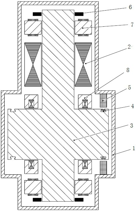
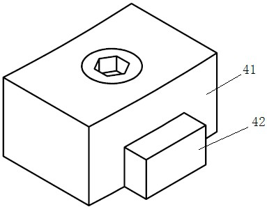
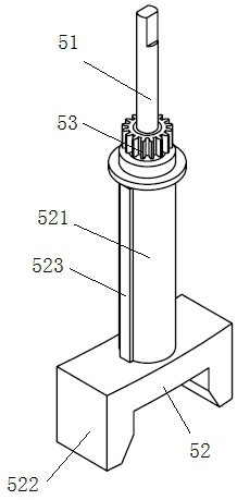
[0027] Such as Figure 1-Figure 8 As shown, the self-balancing flywheel energy storage device in a vacuum environment according to the embodiment of the present invention includes a housing 1 , a motor 2 , a flywheel rotor 3 , a plurality of counterweights 4 , a signal acquisition component 6 and a control component 5 . It should be noted that the self-balancing flywheel energy storage device in a vacuum environment is a high-speed rotating body with a large moment of inertia, and the interior of the device is in a vacuum state during operation. The self-balancing flywheel energy storage device in a vacuum environment of this application adopts The radial magnet...


PUM


Abstract

The invention discloses a flywheel energy storage device capable of automatically balancing in a vacuum environment, and the flywheel energy storage device capable of automatically balancing in the vacuum environment comprises a housing, a motor, a flywheel rotor, a plurality of counterweight parts, a signal collection assembly and a control assembly, the plurality of counterweight parts are arranged on the flywheel rotor and can be locked and released with the flywheel rotor, the signal acquisition assembly is in communication connection with the control assembly, the signal acquisition assembly can calculate the unbalanced mass of the flywheel rotor, and the control assembly can control any one of the plurality of counterweight parts to be locked and released with the flywheel rotor according to the unbalanced mass of the flywheel device. According to the flywheel energy storage device capable of balancing automatically in the vacuum environment, on the premise that the flywheel energy storage device is not disassembled and an operation window is not reserved, online dynamic balance of the flywheel rotor can be achieved, and efficient operation and sealing performance of the flywheel energy storage device are guaranteed.

Description

technical field [0001] The invention relates to the technical field of flywheel energy storage, in particular to a flywheel energy storage device that automatically balances in a vacuum environment. Background technique [0002] The balancing process of the flywheel rotor in the relevant technology includes offline dynamic balancing and online dynamic balancing. Offline dynamic balancing needs to be carried out on a balancing machine, which is costly and difficult to guarantee the balance accuracy due to the inconsistency between the rotating speed and the working speed during balancing. [0003] However, when the online dynamic balance in the related art increases or reduces the weight of the flywheel, it is necessary to reserve an operation window or disassemble the open flywheel. There are various problems in both methods. For example, the reserved operation window will affect the airtightness of the flywheel energy storage device. , and repeated disassembly of the flywhe...

Claims


Application Information

Patent Timeline
Patent Type & Authority Applications(China)
IPC IPC(8): H02K7/02H02K7/04H02K7/10H02K11/21H02J15/00
CPCH02K7/025H02K7/04H02K7/10H02K11/21H02J15/007Y02E60/16
Inventor 王志强苏森韩坤陈胜林卜庆瑞
Owner HUACHI KINETIC ENERGY (BEIJING) TECH CO LTD
Why Eureka
Try Eureka