A Liquid Injection and Drainage Online Dynamic Balancing Head Structure for High Rotational Speeds

A technology of liquid injection and drainage, high speed, applied in the field of dynamic balance, can solve the problems of high cost, lack of balance ability, poor safety, etc., and achieve the effect of high safety, strong practicability, and simplified structure

Inactive Publication Date: 2017-10-20
XI AN JIAOTONG UNIV
View PDF6 Cites 0 Cited by
  • Summary
  • Abstract
  • Description
  • Claims
  • Application Information

AI Technical Summary

Problems solved by technology

However, the structure of this device can only inject liquid but not discharge liquid, so that it cannot have a continuous balance ability. When the liquid storage chamber is full of liquid, it must be stopped to clean up the liquid, so that the balance head can continue to work. At the same time, the traditional process also uses a solenoid valve. To realize the outflow of liquid, but in the process of controlling the solenoid valve, it is necessary to introduce current, so that the current is easily introduced into the balance head, the safety is poor, and the cost is high

Method used


Image

  • A Liquid Injection and Drainage Online Dynamic Balancing Head Structure for High Rotational Speeds
  • A Liquid Injection and Drainage Online Dynamic Balancing Head Structure for High Rotational Speeds
  • A Liquid Injection and Drainage Online Dynamic Balancing Head Structure for High Rotational Speeds

Examples


Embodiment 1

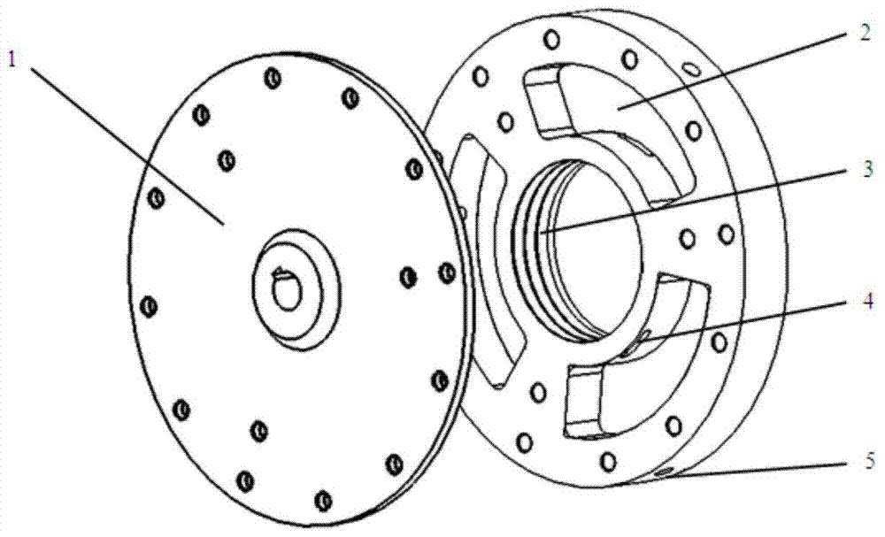
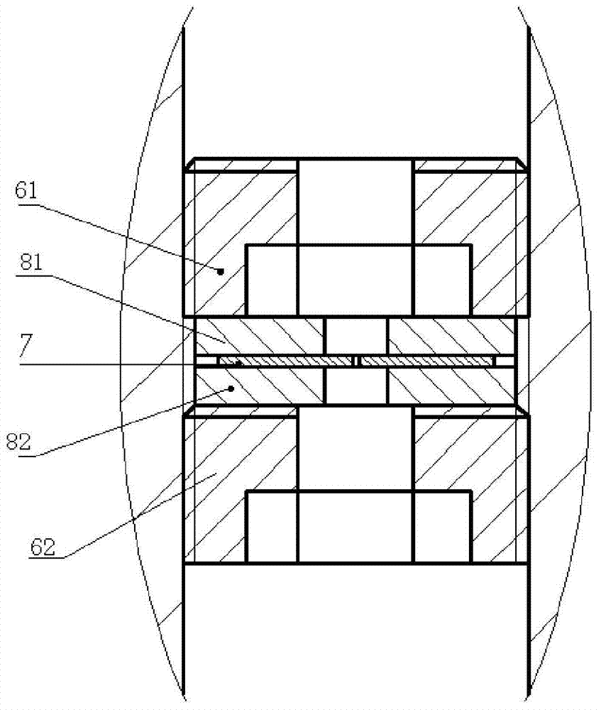
[0025] The inner wall of the second through hole 5 is provided with an internal thread, and the throttle valve includes a first hexagon socket bolt 61, a first gasket 81, a sheet 7, a first hexagonal socket bolt 61, a first gasket 81, a sheet 7, and a second through hole 5 sequentially arranged in the second through hole 5 from the inside to the outside. Two gaskets 82 and the second hexagon socket bolt 62, and the middle part of the first gasket 81 and the second gasket 82 are all provided with the 3rd through hole, the middle part of sheet 7 is provided with the 4th through hole, the 4th through hole and The third through hole, the through hole in the middle of the first hexagon socket bolt 61 and the through hole in the second hexagon socket bolt 62 are connected, and on the outer wall of the first hexagon socket bolt 61 and on the outer wall of the second hexagon socket bolt 62 An external thread matched with the internal bolt is provided.

[0026] The flow rate of the liq...

Embodiment 2

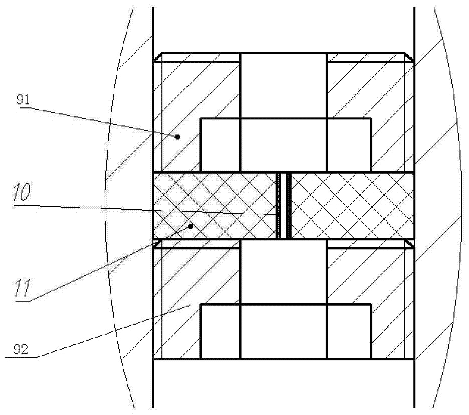
[0028] The inner wall of the second through hole 5 is provided with an internal thread, and the throttle valve includes a third hexagon socket bolt 91, a rubber sheet 11 and a fourth hexagon socket bolt 92 which are sequentially arranged in the second through hole 5 from the inside to the outside. , and the fifth through hole 10 on the rubber sheet 11, the fifth through hole 10 communicates with the through hole in the middle of the third inner hexagon bolt 91 and the through hole in the middle of the fourth inner hexagon bolt 92, the outer wall of the third inner hexagon bolt 91 External threads matching the internal threads are provided on the upper and outer walls of the fourth hexagon socket head bolt 92 .

[0029] Then the flow rate of the liquid flowing out of the throttle valve is Wherein Δp is the pressure difference between the empty inlet and outlet of the fifth through hole 10, d is the inner diameter of the fifth through hole 10, μ is the dynamic viscosity of the ...


PUM


Abstract

The invention discloses a liquid injection and draining type on-line dynamic balance head structure for high rotation speed conditions. The liquid injection and draining type on-line dynamic balance head structure comprises a chassis and a water channel cover; the side face of the chassis is provided with a first through hole and a plurality of liquid storage cavities, the liquid storage cavities are evenly distributed in the periphery of the first through hole, and a plurality of annular grooves which are parallel are formed in the inner wall of the first through hole in the circumferential direction; liquid inlet holes communicated with the corresponding liquid storage cavities are formed in the bottoms of the annular grooves; the outer side of the chassis is provided with a plurality of second through holes communicated with corresponding liquid storage cavities respectively, and throttle valves are arranged in the second through holes respectively; and the water channel cover is fixed to the lateral face of the chassis. By means of the liquid injection and draining type on-line dynamic balance head structure, on-line dynamic balance of a grinding wheel can be rapidly and continuously achieved, stopping for liquid removing is not needed, and the current does not need to be led in.

Description

technical field [0001] The invention belongs to the field of dynamic balance, and relates to a liquid injection and discharge type online dynamic balance head structure used in the case of high rotating speed. Background technique [0002] In recent years, major industrial countries have successively invested a lot of manpower, material resources and financial resources to research and promote high-speed grinding technology. The high-speed grinding technology is a qualitative change in the grinding process, the grinding efficiency and the machining accuracy of the parts are significantly improved, and it is easier to realize automatic grinding. Especially in recent years, the demand for processing brittle and hard materials such as ceramics, optical glass, and single crystal silicon has greatly promoted the research and promotion of high-speed grinding technology. As a key component of a grinding machine, the grinding wheel directly affects the machining process capability ...

Claims


Application Information

Patent Timeline
Patent Type & Authority Patents(China)
IPC IPC(8): B24B41/04B24B49/16
CPCB24B41/042B24B49/165
Inventor 张西宁刘旭
Owner XI AN JIAOTONG UNIV
Why Eureka
Try Eureka