
Transmission device, reception device, communication system, control circuit, communication method, and storage medium

A technology of a sending device and a receiving device, which is applied in the fields of a sending device, a receiving device, a communication system, a control circuit, communication, and a storage medium, and can solve problems such as difficulty in increasing the probability of restoring sent data, and achieve the goal of increasing the probability of restoring sent data Effect

Pending Publication Date: 2022-04-29
MITSUBISHI ELECTRIC CORP
View PDF1 Cites 0 Cited by
  • Summary
  • Abstract
  • Description
  • Claims
  • Application Information

AI Technical Summary

Problems solved by technology

Therefore, there is a problem that error correction coding is usually performed in wireless communication, but when a module whose internal processing order cannot be changed is used, it is difficult to increase the probability that the transmitted data can be correctly restored according to the request of the system, etc.

Method used


Image

  • Transmission device, reception device, communication system, control circuit, communication method, and storage medium
  • Transmission device, reception device, communication system, control circuit, communication method, and storage medium
  • Transmission device, reception device, communication system, control circuit, communication method, and storage medium

Examples


Embodiment approach 1

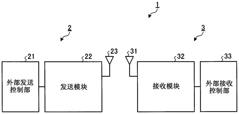
[0035] figure 1 It is a diagram showing the configuration of the communication system 1 according to Embodiment 1 of the present invention. The communication system 1 has a transmitting device 2 and a receiving device 3 . The transmission device 2 has an external transmission control unit 21 , a transmission module 22 and a transmission antenna 23 . The receiving device 3 has a receiving antenna 31 , a receiving module 32 , and an external receiving control unit 33 .

[0036] The transmission module 22 and the reception module 32 are fixed circuits whose internal processing sequence cannot be changed. The fixed circuit is, for example, a general-purpose module that encapsulates functions commonly used by many devices.

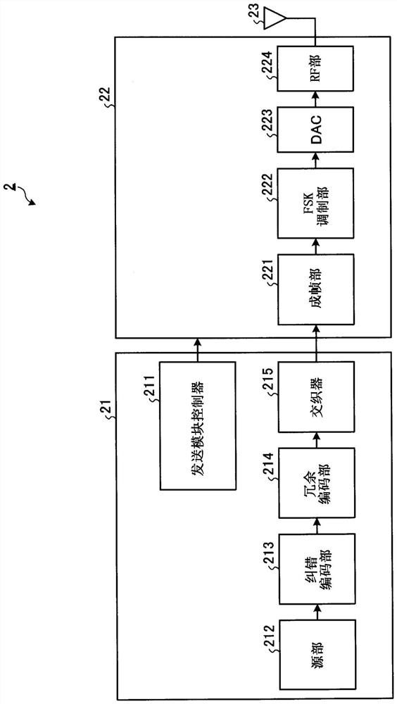
[0037] The external transmission control unit 21 has a function of controlling the transmission module 22 from the outside of the transmission module 22 and a function of supplying transmission data to the transmission module 22 . The transmission module 22...

Embodiment approach 2

[0061] Figure 8 It is a diagram showing the functional configuration of a transmission device 2A according to Embodiment 2 of the present invention. Hereinafter, regarding the functional configuration of the transmission device 2A, the parts different from the transmission device 2 according to Embodiment 1 will be mainly described, and the description of the same parts as the transmission device 2 will be omitted.

[0062] The transmission device 2A has an external transmission control unit 21A, a transmission module 22 , and a transmission antenna 23 . The external transmission control unit 21A has a transmission module controller 211 , a source unit 212 , an error correction coding unit 213 , a redundancy coding unit 214A, and an interleaver 215 . The transmitting device 2A includes a redundant coding unit 214A instead of the redundant coding unit 214 of the transmitting device 2 .

[0063] Figure 9 is for illustration Figure 8 A diagram showing the function of the e...

Embodiment approach 3

[0071] Figure 13 It is a diagram showing the functional configuration of the transmission device 2B according to Embodiment 3 of the present invention. Hereinafter, regarding the functional configuration of the transmission device 2B, parts different from those of the transmission device 2 according to Embodiment 1 will be mainly described, and descriptions of parts similar to those of the transmission device 2 will be omitted.

[0072] The transmission device 2B has an external transmission control unit 21B, a transmission module 22 , and a transmission antenna 23 . The external transmission control unit 21B has a transmission module controller 211 , a source unit 212 , an error correction coding unit 213 , a redundancy coding unit 214B, and an interleaver 215 .

[0073] For application to various systems, it is desirable to be able to flexibly change the redundancy coding rate. In contrast, by thinning out common bits after convolutional coding and then performing redunda...


PUM


Abstract

A transmission device (2) is characterized by being provided with: a transmission module (22) which is a fixed circuit in which the internal processing order cannot be changed, and which performs modulation processing of transmission data; and an external transmission control unit (21) that has a transmission module controller (211) that controls the transmission module (22) in accordance with a redundancy encoding process for converting the multi-value sequence on the reception side, and a redundancy encoding unit (214) that performs redundancy encoding on the transmission data using an error correction encoding sequence and performs redundancy encoding on the transmission data using the error correction encoding sequence. And an external transmission control unit (21) that supplies the transmission module (22) with a redundant coding sequence obtained by redundant coding of transmission data.

Description

technical field [0001] The present invention relates to a transmitting device, a receiving device, a communication system, a control circuit, a communication method, and a storage medium using a fixed circuit whose internal processing sequence cannot be changed. Background technique [0002] Commonly used functionality is sometimes provided as a generic module. A general-purpose module is a fixed circuit whose internal processing order cannot be changed. In the communication field, frequently used functions such as high-frequency processing functions and digital modulation and demodulation processing functions are provided as modules. For example, Patent Document 1 discloses a demodulation method for FSK (Frequency Shift Keying) signals. Frequently used functions such as modulation processing and demodulation processing can reduce the time and labor for repeated development by using a common module. [0003] prior art literature [0004] patent documents [0005] Patent...

Claims


Application Information

Patent Timeline
Patent Type & Authority Applications(China)
IPC IPC(8): H04L1/08H03M13/23H03M13/43
CPCH04L1/08H03M13/23H04B1/12H04B1/16H04L1/0045H04L1/0059H04L1/0061H03M13/3769H03M13/45H04L1/246
Inventor 中岛昭范东中雅嗣
Owner MITSUBISHI ELECTRIC CORP
Learn More