Small intelligent unmanned aerial vehicle for aerial photography
An unmanned aerial vehicle and small-scale technology, applied in the field of aerial photography drones, can solve the problems of inconvenience for photographers to carry, inability to provide buffering effect, and easily damaged equipment, so as to meet the requirements of carrying and using in the field, avoid random swing, and avoid equipment damage Effect
- Summary
- Abstract
- Description
- Claims
- Application Information
AI Technical Summary
Problems solved by technology
Method used
Image
Examples
Embodiment 1
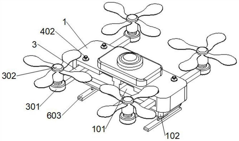
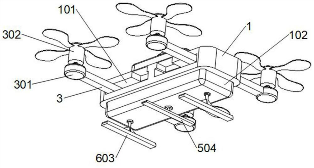
[0033] refer to Figure 1-5 Shown is a small intelligent unmanned aerial vehicle for aerial photography, including a drone body 1, a rotating shaft 2 and a suspension 3. Both sides of the drone body 1 are symmetrically provided with storage side slots 101, and four sets of rotating shafts 2 Correspondingly arranged on the inner side of the four sets of storage side slots 101, the four sets of suspensions 3 are correspondingly fixedly sleeved on the outside of the rotating shaft 2, and the upper part of the UAV body 1 is provided with a fixing device corresponding to the four sets of rotating shafts 2. A buffer base 102 is fixedly installed under the body 1 , and the bottom of the buffer base 102 is respectively provided with a supporting component and a buffer component that cooperate with each other.
[0034] Based on the above structure, the suspension 3 in this device can be stored and unfolded inside the storage side slot 101 through the rotating shaft 2, and at the same t...
Embodiment 2
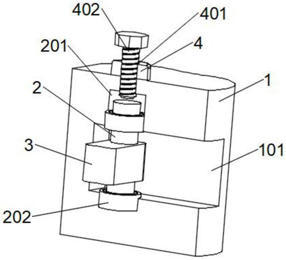
[0036] combine figure 1 , figure 2 and image 3 As shown, based on the above-mentioned embodiment 1, mounting holes 201 are opened on the upper and lower walls of the storage side tank 101, and bearings 202 are embedded and fixed inside the mounting holes 201, and the rotating shaft 2 is rotatably mounted inside the storage side tank 101 through the bearings 202. , and the suspension 3 is installed inside the storage side groove 101 through the rotating shaft 2, the bearing 202 can provide a certain rotation effect for the rotating shaft 2, and then the suspension 3 can rotate inside the storage side groove 101 through the rotating shaft 2, which facilitates the suspension 3 expansion and storage.
Embodiment 3
[0038] combine figure 1 and figure 2As shown, based on the above-mentioned embodiment 1 or 2, the end of the suspension 3 away from the rotating shaft 2 is embedded and fixed with a drive motor 301, and the output end of the drive motor 301 penetrates above the end of the suspension 3, and the drive motor 301 outputs A detachable rotor 302 is bolted to the end, and the drive motor 301 and the rotor 302 are set to be detachable and detachable, which reduces a certain space and facilitates the overall storage of the device.
PUM
 Abstract
Description
Claims
Application Information
 - R&D
- Intellectual Property
- Life Sciences
- Materials
- Tech Scout
- Unparalleled Data Quality
- Higher Quality Content
- 60% Fewer Hallucinations
Browse by: Latest US Patents, China's latest patents, Technical Efficacy Thesaurus, Application Domain, Technology Topic, Popular Technical Reports.
© 2025 PatSnap. All rights reserved.Legal|Privacy policy|Modern Slavery Act Transparency Statement|Sitemap|About US| Contact US: help@patsnap.com


