
Vertebral body distraction device

A technology of distractor and vertebral body, which is applied in the field of vertebral body distraction trial to achieve the effects of shortening operation time, improving operation and reducing lamina tissue damage

Pending Publication Date: 2022-05-06
SHANGHAI KINETIC MEDICAL
View PDF0 Cites 0 Cited by
  • Summary
  • Abstract
  • Description
  • Claims
  • Application Information

AI Technical Summary

Problems solved by technology

[0004] The present invention provides a vertebral body spreader, which will solve the technical problem of the cumbersome process of needing to stretch the vertebral body first and then replace the trial mold and find out the specifications of the fusion cage in the existing PLIF / TLIF operation.

Method used


Image

  • Vertebral body distraction device
  • Vertebral body distraction device
  • Vertebral body distraction device

Examples


Embodiment Construction

[0060] In order to more clearly illustrate the embodiments of the present invention or the technical solutions in the prior art, the specific implementation manners of the present invention will be described below with reference to the accompanying drawings. Obviously, the accompanying drawings in the following description are only some embodiments of the present invention, and those skilled in the art can obtain other accompanying drawings based on these drawings and obtain other implementations.

[0061] In order to make the drawing concise, each drawing only schematically shows the parts related to the present invention, and they do not represent the actual structure of the product. In addition, to make the drawings concise and easy to understand, in some drawings, only one of the components having the same structure or function is schematically shown, or only one of them is marked. Herein, "a" not only means "only one", but also means "more than one".

[0062] It should ...


PUM


Abstract

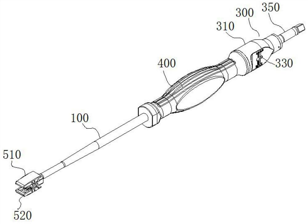
The vertebral body dilator comprises a core tube, a push rod, a tail push mechanism and two distraction plates, the push rod is partially arranged in the core tube, and the two ends of the push rod are located outside the core tube; the tail pushing mechanism is connected to one end of the core tube and connected with the push rod, the tail pushing mechanism is used for driving the push rod to move in the axial direction of the core tube, and an indicating structure is arranged on the tail pushing mechanism; one ends of the two first distraction arms are movably connected to the push rod and the core tube respectively, and one ends of the two first distraction arms are movably connected to the push rod and the core tube respectively; the two distraction plates are movably connected to the other end of the first distraction arm and the other end of the second distraction arm respectively. In an opening state, the tail pushing mechanism drives the push rod to move towards the tail pushing mechanism, so that each group of opening arms are opened, and the two opening plates are opened in parallel; and in the folding state, the two opening plates are folded.

Description

technical field [0001] The invention relates to the technical field of vertebral body distraction testing, in particular to a vertebral body distractor. Background technique [0002] PLIF / TLIF is the most widely used thoracolumbar interbody fusion at home and abroad. During the operation, it is necessary to remove the degenerated intervertebral disc or the nucleus pulposus that has compressed the nerve, and use the spreader and trial mold to expand the upper and lower vertebral bodies for reduction. At the same time, find out the most suitable specifications for physiological needs, and then implant the corresponding The standard fusion device implant can achieve the removal of symptoms and meet the normal physiological curvature of the human spine. In the process of restoring the distracted vertebral body, it is necessary to insert, rotate, and remove the spreaders of different specifications in order from small to large, and finally insert the trial mold to find out the f...

Claims


Application Information

Patent Timeline
IPC IPC(8): A61B17/02A61F2/46
CPCA61B17/025A61F2/4601A61F2/4611A61F2/4684A61B2017/0256
Inventor 严武杨志程
Owner SHANGHAI KINETIC MEDICAL
Learn More