Embedded auxiliary fuel tank system

An auxiliary fuel tank and built-in technology, which is applied to the fuel tank of the power unit, weight reduction, etc., can solve the problems of blank integrated design, no technical data, and difficult maintenance and guarantee, so as to reduce the range of oil core variation and ensure reliable oil delivery , the effect of improving the success rate

Active Publication Date: 2022-05-06
CHENGDU AIRCRAFT INDUSTRY GROUP
View PDF23 Cites 0 Cited by
  • Summary
  • Abstract
  • Description
  • Claims
  • Application Information

AI Technical Summary

Problems solved by technology

Third, it is difficult to maintain
However, in today's industry, the integrated design of the fuel system of the embedded sub-tank is still blank, and there is no relevant technical information

Method used


Image

  • Embedded auxiliary fuel tank system
  • Embedded auxiliary fuel tank system
  • Embedded auxiliary fuel tank system

Examples


Embodiment 1

[0034] A built-in sub-tank system, such as Figure 12 As shown, it includes a storage cabin and a delivery cabin separated by a sealed partition 10. The upper part of the storage cabin is provided with a gravity refueling port 2 and an air pipe 4. One side of the storage cabin corresponds to the air pipe 4. There is an air circuit interface; the upper part of the delivery cabin is provided with an oil filling device 6, and one end of the oil filling device 6 passes through one side of the delivery cabin and is provided with an oil circuit interface; it also includes a Y-shaped pipe 3, The connecting pipe 9, the lower part of the storage cabin and the conveying cabin is communicated through the communicating pipe 9, and one end of the communicating pipe 9 located at the conveying cabin is provided with an upturning one-way valve, and the Y-shaped pipe 3 includes a connected A nozzle , B nozzle, C nozzle; the gravity filling port 2 is connected with the A nozzle of the Y-shaped ...

Embodiment 2

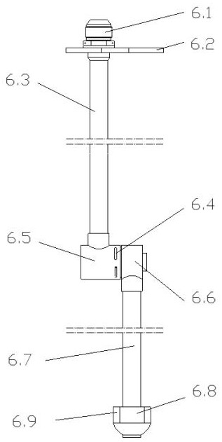
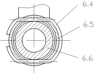
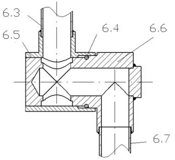
[0041] This embodiment is optimized on the basis of embodiment 1, such as Figure 1-Figure 3As shown, the oil filling device 6 includes a nozzle 6.1, an oil delivery pipe 6.3, a nipple sleeve 6.5, a pipe joint 6.6, an oil suction pipe 6.7, an eccentric block 6.8, and a counterweight 6.9; one end of the oil delivery pipe 6.3 passes through the nipple sleeve 6.5 It communicates with the pipe joint 6.6 and the oil suction pipe 6.7, the inner sleeve of the vertical elbow of the pipe joint 6.6 rotates in the pipe joint sleeve 6.5, and the other end passes through the delivery cabin and connects the nozzle 6.1; the free of the oil suction pipe 6.7 The end is provided with an eccentric block 6.8 and a counterweight 6.9.

[0042] Further, the oil filling device 6 also includes a U-shaped safety pin 6.4, the vertical elbow of the pipe joint 6.6 is provided with an annular groove along the circumference, and the upper and lower sides of the pipe joint sleeve 6.5 are respectively provide...

Embodiment 3

[0046] This embodiment is optimized on the basis of embodiment 1 or 2, as Figure 7 As shown, the gravity filling port 2 includes a main body, the top of the main body is provided with a blocking cover 2.4, and the side wall is provided with a vent nozzle 2.1, and the bottom sides of the main body are respectively provided with a scale 2.3, and adjacent scales 2.3 The slide between is provided with a float 2.2.

[0047] When the gravity filling port 2 was opened, the vent pipe nozzle 2.1 was connected to the atmosphere, and when the gravity fuel port 2 was closed, the vent pipe nozzle 2.1 was blocked. The ventilation nozzle 2.1 is connected with the A nozzle of the Y-shaped pipe 3 to ensure that the gas in the delivery cabin is discharged smoothly during gravity refueling. The gravity filling port 2 is provided with a float 2.2 in addition to the air nozzle 2.1, which has the function of indicating the liquid level, and is convenient for observing the full oil level during gr...


PUM


Abstract

The invention discloses an embedded auxiliary oil tank system which comprises a storage cabin and a conveying cabin which are arranged in a separated mode, a gravity oil filling port and a gas circuit pipe are arranged on the upper portion in the storage cabin, an oil adding and conveying device is arranged on the upper portion in the conveying cabin, the embedded auxiliary oil tank system further comprises a Y-shaped pipe and a communicating pipe, and the lower portion of the storage cabin is communicated with the lower portion of the conveying cabin through the communicating pipe. An upturning type one-way valve is arranged at the end, located in the conveying cabin, of the communicating pipe, and the Y-shaped pipe comprises a pipe opening A, a pipe opening B and a pipe opening C which communicate with one another; the gravity oil filling port is connected with a pipe opening A of a Y-shaped pipe through a ventilation pipe nozzle, a pipe opening B of the Y-shaped pipe penetrates through the sealing partition plate, communicates with the conveying cabin and is provided with a downward turning type one-way valve, and a pipe opening C of the Y-shaped pipe is located on the lower portion of the interior of the storage cabin and lower than a pipe opening of the communicating pipe. The device has the functions of pressure refueling, gravity refueling, refueling ventilation, oil transportation pressurization, pressure protection, oil pumping and discharging, oil quantity warning and the like, and has good practicability.

Description

technical field [0001] The invention belongs to the technical field of fuel systems in aircraft auxiliary fuel tanks, and in particular relates to a built-in auxiliary fuel tank system. Background technique [0002] The auxiliary fuel tank is used on the aircraft, and its internal fuel system needs to have multiple functions. First, fuel output. Regardless of the flight process of the aircraft, the fuel in the drop tank must be reliably output. Second, refuel and ventilate. There are two ways to add fuel to the auxiliary fuel tank, one is pressure refueling, which is added through the fuel system on the aircraft; the other is gravity refueling, which is added through a ground refueling vehicle. Different refueling methods also need to match the corresponding exhaust methods, and an alarm is required when the fuel is full. Again, put oil on the ground. Cleaning of auxiliary fuel tanks, unused fuel for flight, etc. all need to be quickly discharged during ground maintenan...

Claims


Application Information

Patent Timeline
IPC IPC(8): B64D37/04
CPCB64D37/04Y02T50/40
Inventor 邢荣英程家林汤易梁国浩安玮
Owner CHENGDU AIRCRAFT INDUSTRY GROUP
Why Eureka
Try Eureka