Mechanical hysteresis type vacuum maintaining energy-saving control device

A technology of vacuum maintenance and energy-saving control, applied in conveyor control devices, transportation and packaging, conveyor objects, etc., can solve the problems of low efficiency, waste of high-pressure air source, and high energy consumption, saving control operations and shortening working time. Effect

Pending Publication Date: 2022-05-06
程广云
View PDF0 Cites 2 Cited by
  • Summary
  • Abstract
  • Description
  • Claims
  • Application Information

AI Technical Summary

Problems solved by technology

The vacuum pump saves energy, but it may be necessary to prepare a separate vacuum pump. The vacuum generator can use the original air compressor of the electrical system, so it is convenient and simple to implement, but the disadvantage is that it consumes a lot of energy, and the approximate efficiency is only about 25% of the pumping scheme.
At the same time, when using the vacuum generator, when the negative pressure is in place, if the leakage between the suction cup and the workpiece is small, the air supply is still continuous, which greatly wastes the high-pressure air source. Under the ordinary low-power air source, the vacuum generator has a nozzle with a diameter of 1 mm. Consumed gas needs to be maintained with 1 kilowatt of power, which consumes a lot of energy

Method used


Image

  • Mechanical hysteresis type vacuum maintaining energy-saving control device
  • Mechanical hysteresis type vacuum maintaining energy-saving control device
  • Mechanical hysteresis type vacuum maintaining energy-saving control device

Examples


Embodiment Construction

[0014] For the above-mentioned technical scheme, give preferred embodiments and describe in detail in conjunction with the drawings, see Figure 1 to Figure 3 .

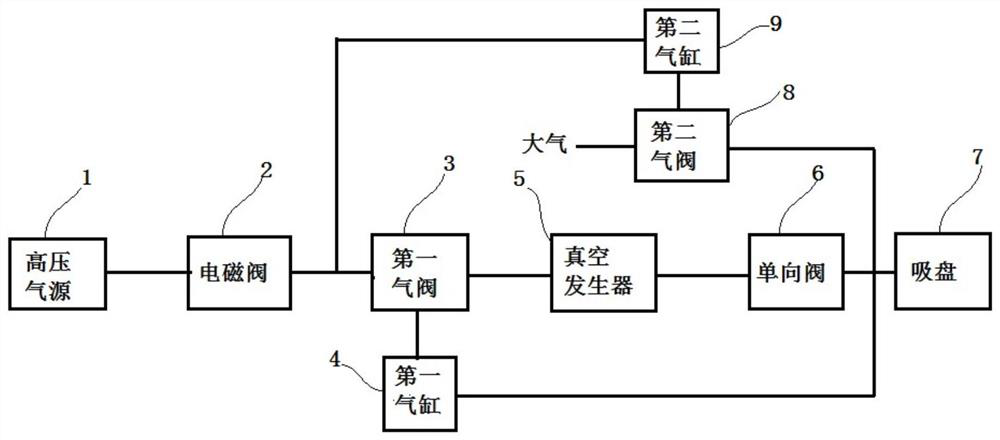
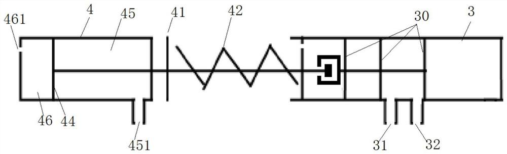
[0015] Mechanical hysteresis vacuum maintenance energy-saving control device, including high-pressure air source 1, solenoid valve 2, first air valve 3, first cylinder 4, vacuum generator 5, one-way valve 6, suction cup 7, second air valve 8, Second cylinder 9. The high-pressure air source 1 is generally an air compressor. The high-pressure air source 1 communicates with the solenoid valve 2 through the air pipe, the solenoid valve 2 is connected to the input end 31 of the first air valve 3 through the air pipe, and the output end 32 of the first air valve 3 is connected to the high-pressure air source input end of the vacuum generator 5 through the air pipe connected, the sealing ring 30 of the first air valve is driven to connect or disconnect the input end 31 and the output end 32 through the valve stem.

[001...


PUM


Abstract

The invention discloses a mechanical hysteresis type vacuum maintaining energy-saving control device which comprises a high-pressure air source, an electromagnetic valve, a vacuum generator and a suction cup. The electromagnetic valve, the vacuum generator and the suction cup are sequentially connected with the high-pressure air source through an air pipe, and a first air valve is arranged on the air pipe between the electromagnetic valve and the vacuum generator. A one-way valve is arranged between the vacuum generator and the suction cup. A valve rod of the first air valve is connected with a piston rod of a first air cylinder, the first air cylinder is communicated with an air pipe between the one-way valve and the suction cup through an air pipe, and springs are arranged on the piston rod and the valve rod between a first air cylinder shell and a first air valve shell in a sleeved mode. By means of a mechanical mode, in the operation process, opening and closing of the air valve are controlled through air pressure changes of an air channel, the pressure maintaining state of the suction cup is achieved, the working time of the vacuum generator is shortened, meanwhile, additional control operation for the air valve is omitted, and energy saving in multiple aspects is achieved.

Description

technical field [0001] The invention relates to the field of manufacturing, in particular to a control device for a vacuum suction cup used for sucking objects in an automatic production process. Background technique [0002] A large number of vacuum suction cups are used as the terminal actuator in industrial automation. There are two ways to generate negative pressure. One is to connect the vacuum suction cup after switching between the vacuum pump and the solenoid valve; The device generates negative pressure and then connected to the vacuum suction cup. Vacuum pumps save energy but may need to be prepared separately. The vacuum generator can use the original air compressor of the electrical system, so it is convenient and simple to implement, but the disadvantage is that it consumes a lot of energy, and the approximate efficiency is only about 25% of the pumping solution. At the same time, when using the vacuum generator, when the negative pressure is in place, if the l...

Claims


Application Information

Patent Timeline
Patent Type & Authority Applications(China)
IPC IPC(8): B65G47/91B65G43/08
CPCB65G47/917B65G43/08
Inventor 程广云
Owner 程广云
Why Eureka
Try Eureka