
Automatic cable winding and unwinding device for mine

A cable and automatic technology, applied in the cable field, can solve the problems of labor-intensive, affecting the laying effect, and the position of the cable is not fixed, and achieves the effect of avoiding manpower, efficient and rapid damage

Pending Publication Date: 2022-05-06
BEIFANG WEIJIAMAO COAL POWER CO LTD
View PDF0 Cites 0 Cited by
  • Summary
  • Abstract
  • Description
  • Claims
  • Application Information

AI Technical Summary

Problems solved by technology

[0003] However, when the existing mine cable unwinding device is in use, operations such as cable coiling, dragging and dropping, and laying need to be done manually. On the reel, the cable is manually pulled outward. Since the cable is usually of high quality, a large amount of manpower is consumed in the operation process, which makes the efficiency very low and affects the cost and progress of the construction, and the manual operation is relatively large. At the same time, due to the large range of the reel, the unwinding device will rotate with the walking of the electric forklift. When releasing the cable, the position of the cable on the reel is relatively uncertain. When the unwinding device pulls the cable outward, The position is easy to shift, which makes the cable routing position shift and affects the laying effect

Method used


Image

  • Automatic cable winding and unwinding device for mine
  • Automatic cable winding and unwinding device for mine
  • Automatic cable winding and unwinding device for mine

Examples


Embodiment 1

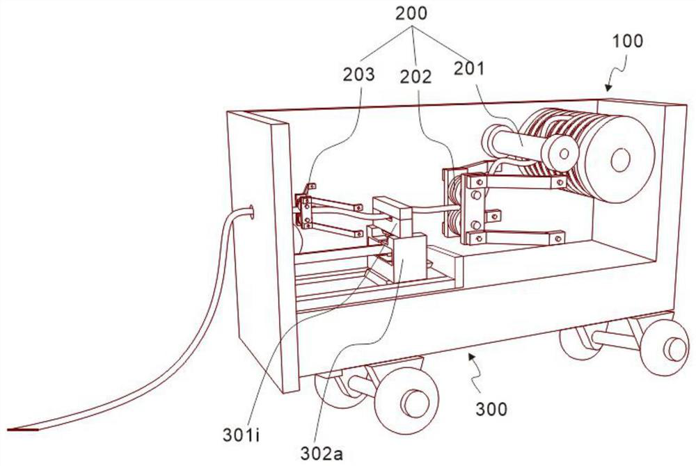
[0030] refer to figure 1 and figure 2 , which is the first embodiment of the present invention, this embodiment provides a mine cable automatic unwinding device, the mine cable automatic unwinding device includes a placement assembly 100, a limit assembly 200 and a pulling assembly 300, and the cable is wound when in use On the placement component 100, one end passes through the limit component 200 and pulls the component 300 out of the device, which can limit the displacement of the cable, protect the cable from winding properly, and reduce the damage caused by winding.

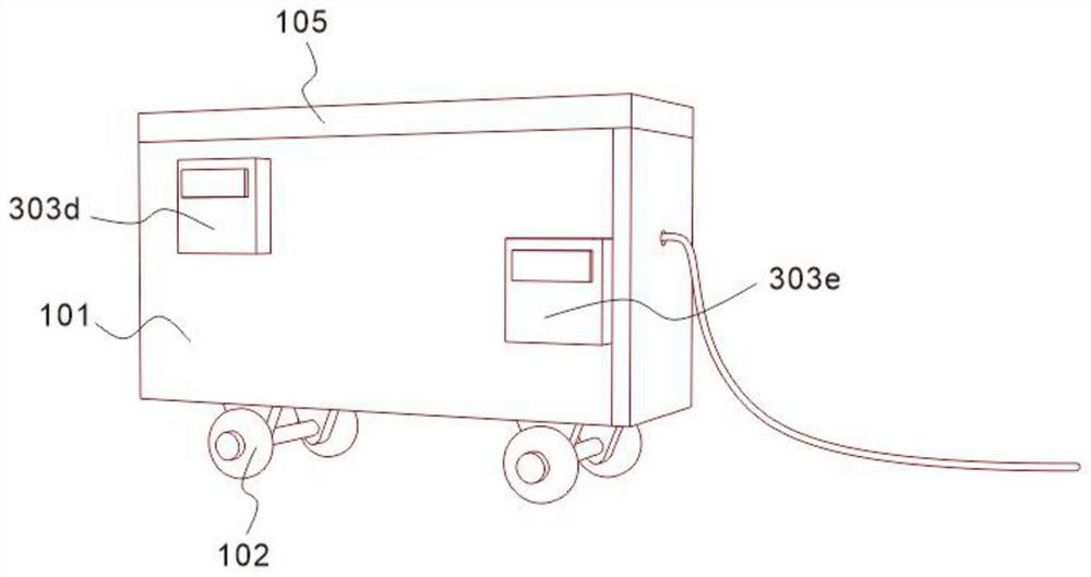
[0031] Specifically, the placement assembly 100 includes a placement box 101 and rubber wheels 102, the rubber wheels 102 are arranged at the bottom of the placement box 101, and the rubber wheels 102 are movable casters, which can be locked by stepping on the movable caster baffle to make the device unable to move.

[0032] Specifically, the limit assembly 200 includes a limit roller 201, which is arrange...

Embodiment 2

[0036] refer to Figure 2-7 , is the second embodiment of the present invention, which is based on the previous embodiment.

[0037] Specifically, the placement assembly 100 also includes a reel 103, which is arranged inside the placement box 101, and a fixed plate 104, which is fixed on the inner bottom surface of the placement box 101 and connected to the other side of the moving part 302, and also includes a placement box cover 105. , is arranged on the top of the placement box 101, the reel 103 is on the inner side of the placement box 101 for winding and storage of cables, and the case cover 105 is for the placement box 101 to be covered.

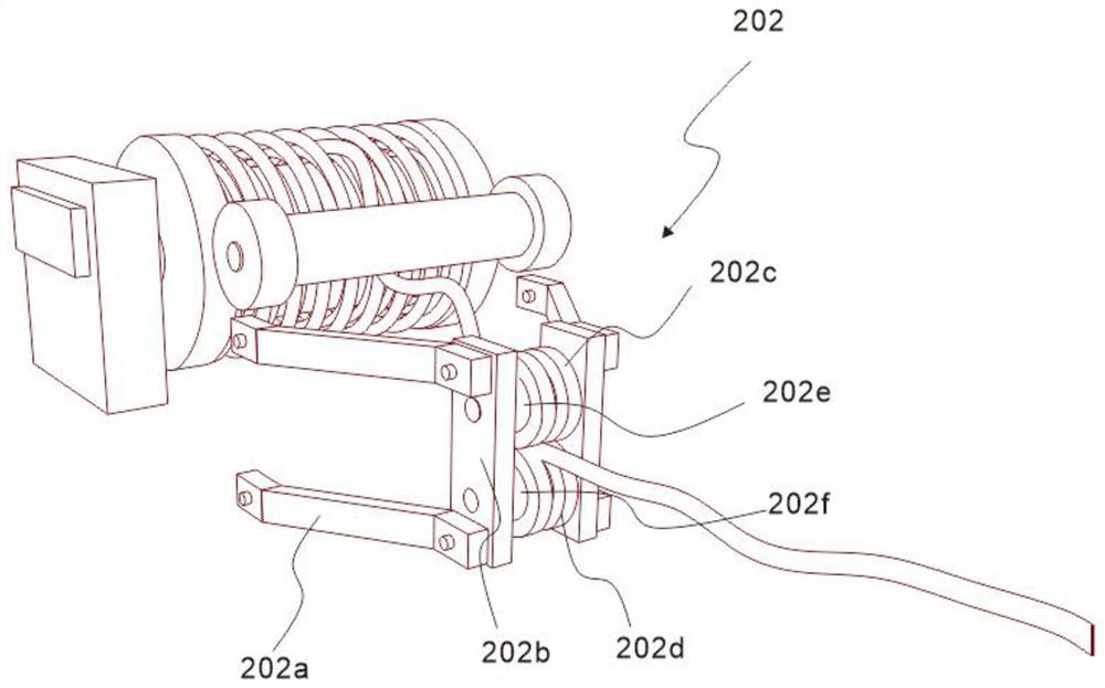
[0038] Specifically, the first limiter 202 includes a first folded plate 202a, one side of the first folded plate 202a is fixedly connected to the inner wall of the storage box 101, the first limiter 202 also includes a first vertical plate 202b, the first vertical plate The straight plate 202b is fixedly connected to the other side o...

Embodiment 3

[0042] refer to Figure 2-7 , is the third embodiment of the present invention, which is based on the first two embodiments.

[0043] Specifically, the top of the clamping member 301 is provided with a clamping block 301a, the bottom of the clamping block 301a is provided with an insertion groove 301b, the inner wall of the insertion groove 301b is fixed with a support block 301c, the bottom of the support block 301c is provided with a clamping plate 301d, and the clamping plate 301d is provided with a placement groove 301e in the middle, and the support block 301c is placed on the top of the placement groove 301e. The bottom of the clamping plate 301d is provided with a telescopic rod 301f, and the bottom of the telescopic rod 301f is provided with a splint 301g. The lower splint part 301g-2, the expansion rod 301f is connected through the splint part 301g, the splint part 301g also includes a splint spring 301g-3, which is arranged at the bottom of the lower splint part 301g...


PUM


Abstract

The invention discloses an automatic cable winding and unwinding device for a mine, and the device comprises a placement assembly which comprises a placement box body and a rubber wheel, and the rubber wheel is disposed at the bottom of the placement box body; the limiting assembly comprises a limiting roller arranged on the inner wall of the containing box body, a first limiting piece arranged on one side of the limiting roller and a second limiting piece arranged on one side of the first limiting piece. And the pulling assembly comprises a clamping piece arranged between the second limiting piece and the first limiting piece, a moving piece arranged at the bottom of the clamping piece, and a transmission piece arranged on one side of the moving piece. According to the device, through cooperation of the placing assembly, the limiting assembly and the pulling assembly, the cable can be automatically laid or recycled, waste of a large amount of manpower is avoided, meanwhile, the position of the cable is fixed, the situation that the laying effect is affected by cable deviation is avoided, cable laying and recycling are efficient and rapid, and damage is small.

Description

technical field [0001] The invention relates to the technical field of cables, in particular to an automatic cable unwinding device for mines. Background technique [0002] With the continuous improvement of the mechanization of coal mine equipment, large-scale electric traction mobile equipment (such as roadheaders, continuous mining machines, shuttle cars, etc.) are more and more widely used in mines due to their advantages of energy saving, environmental protection, and high degree of integrated control. Mine cables have high voltage (1140V) and have explosion-proof requirements. Their dimensions and weight are large. As the electric forklift moves, the cables directly rub against the ground and sharp stones, which seriously damages the working equipment. Therefore, they are often used The unwinding device winds the cable directly onto the reel. [0003] However, when the existing mine cable unwinding device is in use, operations such as cable coiling, dragging and dropp...

Claims


Application Information

Patent Timeline
IPC IPC(8): B65H75/42B65H75/44B65H75/48
CPCB65H75/48B65H75/4486B65H75/4457B65H75/44B65H75/4405B65H75/425B65H2701/34
Inventor 许文杰张飞张悦芳李德利崔志远张永贵杨海军李钊
Owner BEIFANG WEIJIAMAO COAL POWER CO LTD
Learn More