A kind of pneumatic centrifugal spray construction inspection well repair equipment, engineering vehicle and repair method

An inspection well and pneumatic technology, which is applied in hydraulic engineering, infrastructure engineering, infrastructure repair and other directions, can solve the problems of easy collision, damage to the lining slurry layer by spraying, and easy swing of the pneumatic rotary spray device, so as to avoid The effect of swing, quality assurance, and large expansion and contraction

Active Publication Date: 2022-08-02
广东银浩智能技术有限公司
View PDF7 Cites 1 Cited by
  • Summary
  • Abstract
  • Description
  • Claims
  • Application Information

AI Technical Summary

Problems solved by technology

However, when the repair equipment is in use, when the gas enters and exits the pneumatic swirl spray device, it will generate a driving force on the pneumatic swirl spray device, causing the pneumatic swirl spray device to swing, which will affect the quality of spraying. At the same time, the swing of the pneumatic swirl spray device is easy Colliding with the side wall of the inspection well, destroying the sprayed lining slurry layer
[0004] In view of the above-mentioned related technologies, the inventor believes that there is a defect that the pneumatic swirl spray device of the repair equipment in the related technology is easy to swing

Method used


Image

  • A kind of pneumatic centrifugal spray construction inspection well repair equipment, engineering vehicle and repair method
  • A kind of pneumatic centrifugal spray construction inspection well repair equipment, engineering vehicle and repair method
  • A kind of pneumatic centrifugal spray construction inspection well repair equipment, engineering vehicle and repair method

Examples


Embodiment Construction

[0038] Attached to the following Figure 1-5This application will be described in further detail.

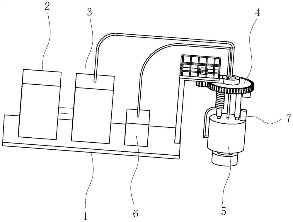
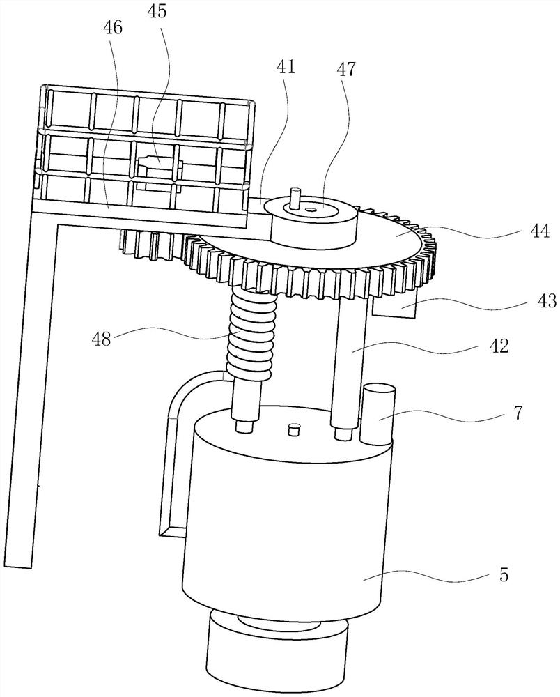
[0039] The embodiment of the present application discloses a pneumatic centrifugal jetting inspection well repair equipment. refer to figure 1 and figure 2 , a pneumatic centrifugal jetting inspection well repair equipment, including a supporting device 1, a pulping device 2, a pumping device 3, a lifting device 4 and a pneumatic rotary jetting device 5, the supporting device 1 includes a base, when in use, the base is installed on the On the ground, the pulping device 2, the pumping device 3 and the lifting device 4 are respectively installed on the base. The pumping device 3 is respectively connected to the pulping device 2 and the pneumatic rotary jetting device 5. The lifting device 4 is connected to the pneumatic rotary jetting device 5 and drives the pneumatic rotary jetting device 5 to ascend and descend. The pneumatic rotary jetting device 5 is provided with a lockin...


PUM


Abstract

The invention relates to a kind of pneumatic centrifugal jetting inspection well repair equipment, which comprises a supporting device, a pulping device, a pumping device, a lifting device and a pneumatic rotary jetting device, and the pneumatic rotary jetting device is provided with a locking device for the pneumatic rotary jetting. The locking structure of the pneumatic rotor of the device; the lifting device includes a boom, a lifting rod, a lifting pump, a rotary table and a rotating motor, one end of the boom is installed on the support device, and the other end of the boom rotates The rotary table is connected to the rotary table, and the rotary motor is connected to the rotary table and drives the rotary table to rotate. The rotary motor is installed on the suspension arm, and the upper end of the lifting rod is fixed on the rotary table. The lift rod is connected to the lift pump, the lift pump is installed on the rotary table, and the lower end of the lift rod is fixedly connected to the pneumatic rotary spray device. The present application has the effect of improving the defect that the pneumatic rotary spray device is easy to swing.

Description

technical field [0001] The invention relates to the field of inspection well repair, in particular to a pneumatic centrifugal jetting inspection well repair equipment, an engineering vehicle and a repair method. Background technique [0002] The urban underground pipeline network is an important infrastructure construction of the city, and it is the "underground lifeline" to ensure the normal operation of the urban functions as a whole. With the continuous acceleration of urbanization in my country, the amount of urban underground pipeline expansion and renovation projects continues to increase. As an important part of the drainage system, inspection wells are known as the "windows" of drainage pipelines. An inspection well is set every 40m of drainage pipelines on average. According to rough statistics, there are currently only 15.75 million drainage inspection wells in cities across the country, which need to be repaired urgently. [0003] The related art discloses a pneu...

Claims


Application Information

Patent Timeline
Patent Type & Authority Patents(China)
IPC IPC(8): E02D15/04E02D37/00E02D29/12
CPCE02D15/04E02D37/00E02D29/125E02D2250/0023
Inventor 谢颖娜陈少华李宇余梦龙
Owner 广东银浩智能技术有限公司
Why Eureka
Try Eureka