Environment-friendly cast-in-place pile construction device for constructional engineering

A technology for construction engineering and construction equipment, which is applied in construction, foundation structure engineering, sheet pile walls, etc., and can solve problems affecting the bearing capacity of cast-in-place piles, uneven dispersion of crushed stones, and cumbersome construction steps

Active Publication Date: 2022-05-06
MINGDA MARINE ENG CO LTD
View PDF9 Cites 0 Cited by
  • Summary
  • Abstract
  • Description
  • Claims
  • Application Information

AI Technical Summary

Problems solved by technology

[0004] In order to overcome the cumbersome construction steps of cast-in-situ piles divided into inner and outer layers, and the uneven dispersion of crushed stones will affect the bearing capacity and service life of cast-in-place piles, the present invention provides a construction device for environmentally friendly cast-in-situ piles

Method used


Image

  • Environment-friendly cast-in-place pile construction device for constructional engineering
  • Environment-friendly cast-in-place pile construction device for constructional engineering
  • Environment-friendly cast-in-place pile construction device for constructional engineering

Examples


Embodiment 1

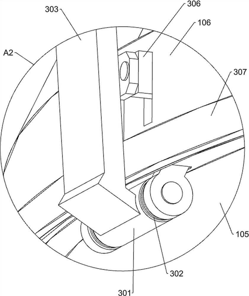
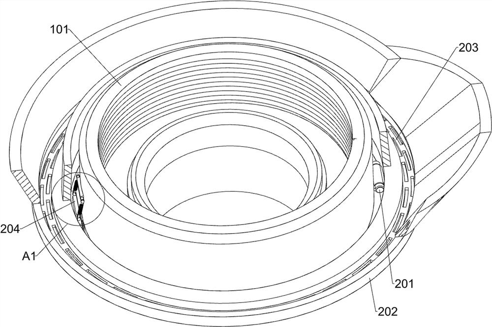
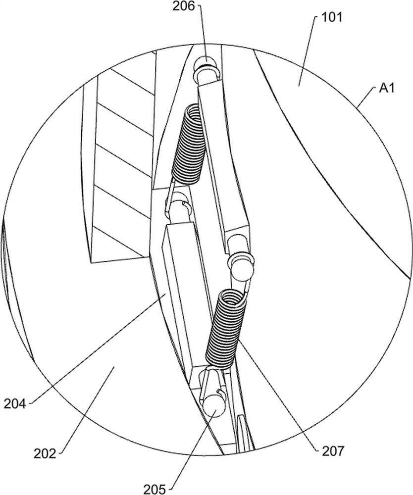
[0032] The utility model relates to an environmental protection cast-in-place pile construction device for construction engineering, such as Figure 1 , and Figure 5 - Figure 12 As shown in, it includes a filling unit, a vibration distribution unit, a bulk material unit, a slurry guide pipe 4 and a material guide pipe 5; The right side of the lower end of the slurry guide pipe 4 is fixedly connected with the material guide pipe 5; The lower end of the slurry guide pipe 4 is connected with a filling unit; The upper side of the filling unit is connected with a vibration distribution unit; The middle part of the filling unit is connected with a bulk material unit; The filling unit comprises a pipe sleeve 101, a slurry conveying pipe 102, an annular isolation plate 103, an annular support frame 104, an annular slider 105 and an annular bulk tray 106; The outer surface of the slurry guide pipe 4 is provided with a stiffener structure; The lower end of the slurry guide pipe 4 is connecte...

Embodiment 2

[0043] as Figure 1 , and Figure 5-14 As shown, this embodiment is further optimized on the basis of embodiment 1, and also includes a debris cleaning unit. The annular bulk tray 106 is provided with a debris cleaning unit. The debris cleaning unit includes a second shaft sleeve 401, a second torsion spring 402, a side fixing rod 403, a spike 404 and an anti-skid roller 405; Four second shaft sleeves 401 are respectively connected around the upper side of the annular bulk disc 106 through a rotating shaft; A second torsion spring 402 is fixedly connected between the two axial ends of the four second shaft sleeves 401 and the annular bulk disc 106, and the second torsion spring 402 is sleeved on the outer surface of the rotating shaft of the adjacent second shaft sleeve 401 shaft; A side fixing rod 403 is welded on the outside of the three second shaft sleeves 401; The upper sides of the three side fixing rods 403 are fixedly connected with a plurality of spikes 404; The outer ends ...


PUM


Abstract

The invention relates to the field of constructional engineering, in particular to an environment-friendly cast-in-place pile construction device for constructional engineering. The technical problems that the construction steps of a cast-in-place pile divided into an inner layer and an outer layer are tedious, and the bearing capacity and the service life of the cast-in-place pile are affected if gravel materials forming an outer column layer of the cast-in-place pile are not evenly dispersed are solved. The environment-friendly cast-in-place pile construction device for constructional engineering comprises a filling unit, a vibration distribution unit and the like. And the upper side of the filling unit is connected with a vibration distribution unit for uniformly distributing crushed stone materials. The isolation type pouring component is arranged, the inner column layer is poured out in a layer-by-layer pouring mode, the outer layer is obtained through overflowing, meanwhile, gravel materials are evenly scattered in slurry of the outer layer through the gravel material dispersing component to form the outer column layer, then the heights of the inner column layer and the outer column layer are sequentially increased, and the inner column layer and the outer column layer are evenly poured out. And rising power is converted into rotating force for uniformly scattering materials, so that the gravel materials are dispersed in slurry of an outer column layer in time.

Description

technical field [0001] The invention relates to the field of construction engineering, in particular to an environmental protection cast-in-place pile construction device for construction engineering. Background technology [0002] In the foundation construction site of construction engineering, cast-in-place piles need to be driven several meters to tens of meters below the bottom layer. The cast-in-place pile construction technology is a concrete technology with low construction cost and simple operation, that is, the concrete slurry penetrates into the depth of the stratum, which can closely combine the stratum with the cast-in-place pile, play a good role in infiltration, compaction and splitting of the stratum, and the interaction between the three can make the stratum more stable. [0003] The existing cast-in-place pile has an internal and external structure. The inner column layer on the inner side is poured by mud alone, while the outer column layer on the outer side is ...

Claims


Application Information

Patent Timeline
Patent Type & Authority Applications(China)
IPC IPC(8): E02D15/04E02D5/34
CPCE02D15/04E02D5/34
Inventor 刘俊男
Owner MINGDA MARINE ENG CO LTD
Why Eureka
Try Eureka