Eureka AIR delivers breakthrough ideas for toughest innovation challenges, trusted by R&D personnel around the world.

Pressure control structure of prefill valve

A technology of pressure control and liquid filling valve, which is applied in the field of hydraulic pressure, can solve the problems of difficult control of the liquid filling interval, achieve the effects of reducing machining accuracy, improving control accuracy, and ensuring flow stability

Active Publication Date: 2022-05-06
ZHEJIANG HAIHONG HYDRAULIC TECH
View PDF6 Cites 0 Cited by
  • Summary
  • Abstract
  • Description
  • Claims
  • Application Information

AI Technical Summary

Problems solved by technology

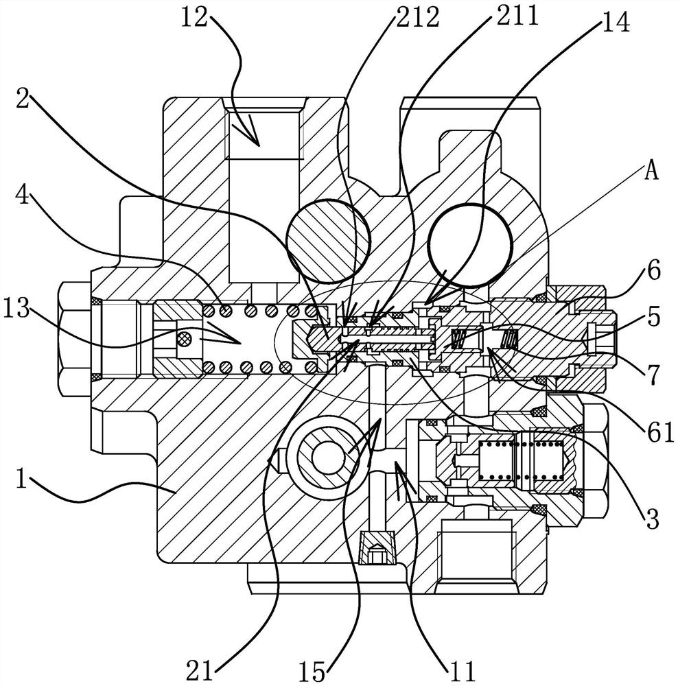
[0005] The purpose of the present invention is to address the above problems existing in the prior art, and propose a pressure control structure of a liquid filling valve to solve the problem of difficult control of the liquid filling interval

Method used


Image

  • Pressure control structure of prefill valve
  • Pressure control structure of prefill valve
  • Pressure control structure of prefill valve

Examples


Embodiment Construction

[0025] The following are specific embodiments of the present invention and in conjunction with the accompanying drawings, the technical solutions of the present invention are further described, but the present invention is not limited to these embodiments.

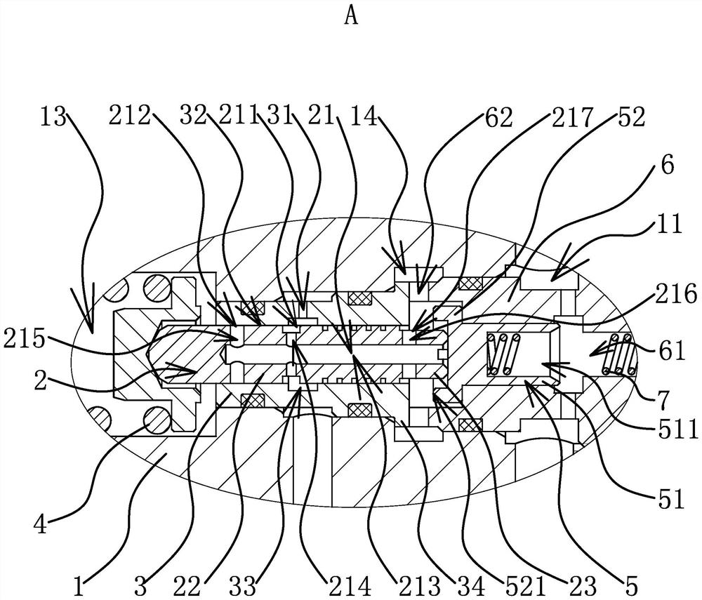
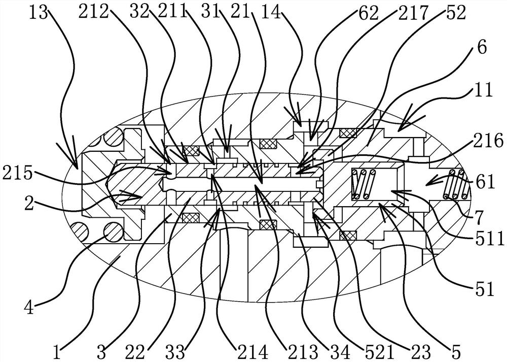
[0026] Such as Figure 1-Figure 5 As shown, the pressure control structure of this filling valve includes a valve body 1 with a filling oil passage 11 and a feedback oil passage 15, the feedback oil passage 15 communicates with the filling oil passage 11, and the filling oil passage 11 has an inflow of oil The oil inlet, the liquid filling port from which the oil supply flows out to the accumulator, the oil outlet 12 from which the oil supply flows back to the fuel tank, and the oil return port for the oil supply to return to the fuel tank, wherein the oil inlet, the filling The liquid port and the oil return port are the necessary openings of the existing liquid filling valve. Since they are not in the same section as the...


PUM


Abstract

The invention provides a pressure control structure of a prefill valve, and belongs to the technical field of hydraulic pressure. The problem that an existing liquid filling interval is difficult to control is solved. The pressure control structure of the prefill valve comprises a valve body with a prefill oil way, an oil outlet through which oil flows out is formed in the valve body, a valve rod with a control oil way is connected in the valve body in a sliding mode, and a spring cavity located at the left end of the valve rod and communicated with the oil outlet and a pressure cavity located at the right end of the valve rod and communicated with the control oil way are formed in the valve body. The control oil way is provided with an inflow port capable of being communicated with the liquid filling oil way and a pressure relief port capable of being communicated with the spring cavity, a valve sleeve which is arranged outside the valve rod in a sleeving mode and can seal the inflow port and / or the pressure relief port is positioned in the valve body, and a pressure spring which elastically abuts against the left end of the valve rod to enable the inflow port to be communicated with the liquid filling oil way is arranged in the spring cavity. A valve element capable of driving the valve rod to move towards the spring cavity so that the pressure relief opening can be communicated with the spring cavity is arranged in the liquid filling oil way. The pressure control structure of the prefill valve has the advantage of reducing the control difficulty of the prefill interval.

Description

technical field [0001] The invention belongs to the technical field of hydraulic pressure and relates to a pressure control structure of a filling valve. Background technique [0002] The braking system is an important component of construction machinery. The mechanical braking technology and gas-hydraulic braking technology widely used in the existing braking system have disadvantages such as small braking torque and poor reliability, which can no longer meet the precision requirements of existing construction machinery. brake. Some manufacturers of hydraulic components not only pay attention to the advantages of high control precision and good stability of hydraulic technology, but also begin to study how to better apply hydraulic technology to the braking system to improve the braking accuracy of the braking system and the braking system. dynamic stability and braking torque. A hydraulic brake system usually includes an oil tank for oil supply and oil return, a hydrauli...

Claims


Application Information

Patent Timeline
Patent Type & Authority Applications(China)
IPC IPC(8): F15B13/02
CPCF15B13/02
Inventor 何贤剑王军王星星钟麒许甫程玲
Owner ZHEJIANG HAIHONG HYDRAULIC TECH
Why Eureka
Eureka Blog
Learn More