Bridge detection device with marking function

A bridge detection and marking technology, which is applied to spraying devices with movable outlets, bridges, bridge construction, etc., can solve the problems of inability to mark hidden danger areas, inconvenient maintenance work, and high cost of use, so as to avoid detection difficulties and facilitate observation. The effect of wide coverage

Pending Publication Date: 2022-05-10
合肥工大工程试验检测有限责任公司
View PDF1 Cites 0 Cited by
  • Summary
  • Abstract
  • Description
  • Claims
  • Application Information

AI Technical Summary

Problems solved by technology

Using these devices, inspectors must work between the lower part of the bridge and the water surface, which is not only expensive to use but also limited in operation, so it is necessary to improve its design
[0003] In the Chinese utility model patent document whose publication number is CN209372346U, a bridge detection device is disclosed. The device is fixed with a sliding rod through a connecting rod at the bottom of the bridge main body. The sliding rod is covered with a detection device. A camera is arranged on the detection device. Real-time detection of the main body of the bridge is realized. By setting the slide rail on the sliding rod and the first gear on the detection device, the first gear drives the detection device to move, and the camera is driven by the second gear to realize the rotation angle of the second motor. Ring, realize the detection of bridges without dead ends, but when detecting areas with potential safety hazards, the hidden areas cannot be marked, which is not convenient for the rapid maintenance work in the later period

Method used


Image

  • Bridge detection device with marking function
  • Bridge detection device with marking function
  • Bridge detection device with marking function

Examples


Embodiment 1

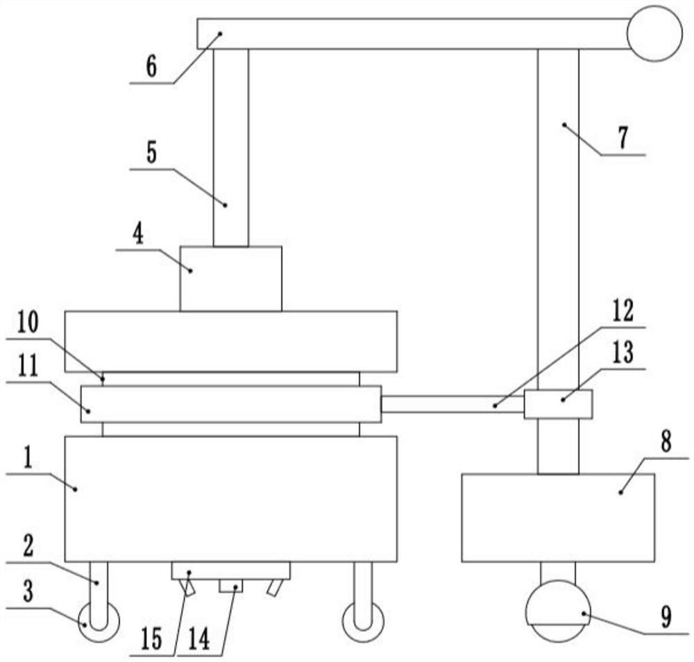
[0023] see Figure 1-3 , a bridge detection device with a marking function, comprising an equipment box 1, the four corners of the bottom end of the equipment box 1 are fixedly connected to the support leg 2, the bottom end of the support leg 2 is rotatably connected to the moving wheel 3, and the top end of the equipment box 1 is fixedly connected to the top Seat 4, the top of the top seat 4 is connected to the rotating column 5 in rotation, the top of the rotating column 5 is fixedly connected to the ejector rod 6, the bottom of the end of the ejector rod 6 away from the rotating column 5 is fixedly connected to the moving rod 7, and the bottom end of the moving rod 7 is fixedly connected to move Seat 8, the bottom end of moving seat 8 is connected with universal roller 9 in rotation, the center of the bottom of equipment box 1 is fixedly connected with detection equipment 14, and the outside of detection equipment 14 is provided with marking device 15.

[0024] The marking ...

Embodiment 2

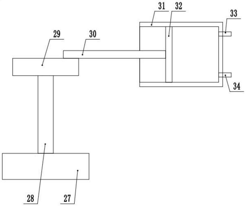
[0032] see Figure 1-3 , the other content of this embodiment is the same as that of Embodiment 1, the difference is that: the outside of the equipment box 1 is provided with a rotating groove 10, and the rotating groove 10 is provided with a first rotating sleeve 11, and the outer sleeve of the moving rod 7 A second rotating sleeve 13 is provided, and a swing rod 30 is fixedly connected between the second rotating sleeve 13 and the first rotating sleeve 11 .

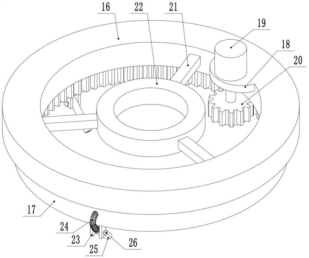
[0033] During the implementation of the present invention, the pushing device can be moved, and the setting of the moving seat 8 can make the movement and placement of the device more stable, and can change the relative position of the moving seat 8 and the equipment box 1, so that the equipment box 1 can be used in a narrow space. When an area with potential safety hazards is detected, the control drive motor 19 starts to drive the ring-shaped rotating seat 17 to rotate, and at the same time, the annular rotating seat ...


PUM


Abstract

The invention discloses a bridge detection device with a marking function, and relates to the technical field of bridge detection.The bridge detection device comprises an equipment box, the bottom ends of supporting legs are rotatably connected with moving wheels, the top end of the equipment box is fixedly connected with a top seat, the top end of the top seat is rotatably connected with a rotating column, and the top end of the rotating column is fixedly connected with a top rod; the bottom end of the moving rod is fixedly connected with a moving seat, the bottom end of the moving seat is rotatably connected with universal wheels, the center of the bottom of the equipment box is fixedly connected with detection equipment, and a marking device is arranged on the outer side of the detection equipment. By arranging the moving seat, the detection equipment can be conveniently placed in spaces of various sizes for detection, the problem of detection difficulty caused by space limitation is avoided, by arranging the marking device, multi-point rotary spraying marking can be carried out when marking is needed, marked positions are in interval characteristics, the coverage is wider, region division is facilitated, and the detection efficiency is improved. The marking property on a detection result is good, and observation of post-processing is facilitated.

Description

technical field [0001] The invention relates to the technical field of bridge detection, in particular to a bridge detection device with a marking function. Background technique [0002] With the development of transportation, the development of bridge construction, which is an important part of transportation, is advancing by leaps and bounds. In order to ensure the safety of traffic participants, after the bridge is completed and put into use, regular inspections must be carried out regularly. Routine inspections of bridges include inspections of the substructure of bridges. The main equipment for this kind of inspection includes scaffolding, work basket and bridge inspection vehicle. Using these devices, inspectors must work between the lower part of the bridge and the water surface, which not only has high cost of use but also limits operations, so it is necessary to improve its design. [0003] In the Chinese utility model patent document whose publication number is ...

Claims


Application Information

Patent Timeline
Patent Type & Authority Applications(China)
IPC IPC(8): B05B3/02B05B9/047E01D19/10
CPCB05B3/02B05B9/047E01D19/106
Inventor 杨善武蒙娇潘星
Owner 合肥工大工程试验检测有限责任公司
Why Eureka
Try Eureka