Laser cutting method and laser cutting system

A laser cutting and laser beam technology, applied in laser welding equipment, glass cutting equipment, glass manufacturing equipment, etc., can solve the problems of substrate separation, poor control of process parameters, and difficulty in obtaining high-quality surface cutting effects, etc., to achieve Guaranteed effect of successful separation

Active Publication Date: 2014-05-07
HEFEI XINSHENG OPTOELECTRONICS TECH CO LTD +1
View PDF3 Cites 28 Cited by
  • Summary
  • Abstract
  • Description
  • Claims
  • Application Information

AI Technical Summary

Problems solved by technology

However, for this kind of cutting method for highly chemically strengthened glass substrates, due to the strengthening of the material hardness on the surface of the glass substrate, the process parameters are difficult to grasp. When the power is high, it is difficult to obtain high-quality surface cutting effects. When the power is low , and the substrate cannot be separated successfully, so it cannot be widely used for cutting highly chemically strengthened glass substrates
[0005] For other pulse laser cutting with lower power, when it is applied to the cutting of highly chemically strengthened glass substrates, due to the characteristics of the pulse laser beam, after laser scanning, a series of continuous thin lines are formed inside the glass substrate. These thin lines are combined to form a cutting line for pulsed laser cutting, but it cannot separate the substrate, so it cannot be applied to cutting of highly chemically strengthened glass substrates.

Method used


Image

  • Laser cutting method and laser cutting system
  • Laser cutting method and laser cutting system
  • Laser cutting method and laser cutting system

Examples


Embodiment Construction

[0050] In order to make the technical problems, technical solutions and advantages to be solved by the present invention clearer, the following will describe in detail with reference to specific embodiments and accompanying drawings.

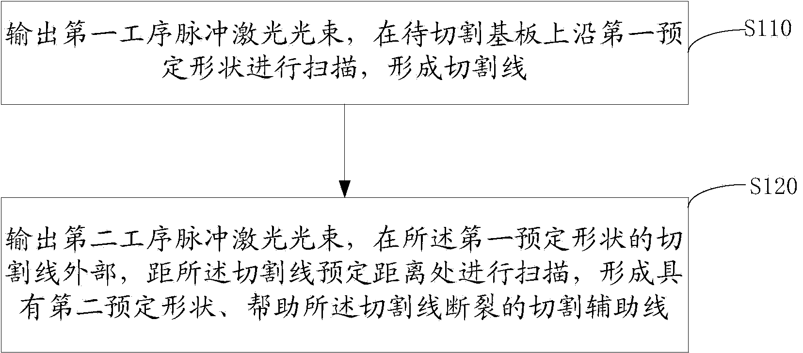
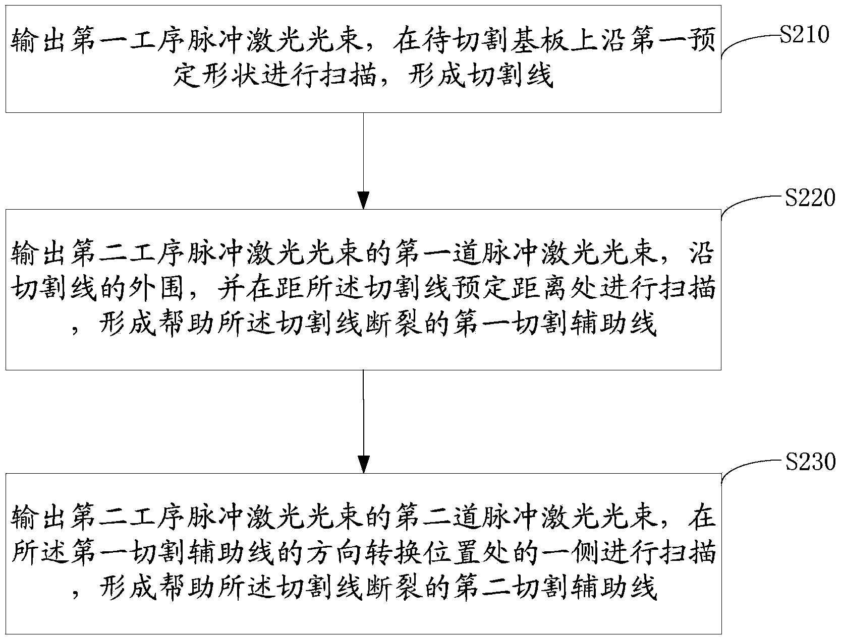
[0051] The laser cutting method of the present invention includes:

[0052] Forming a cutting line with a first predetermined shape on the substrate to be cut; wherein the first predetermined shape is the shape to be cut;

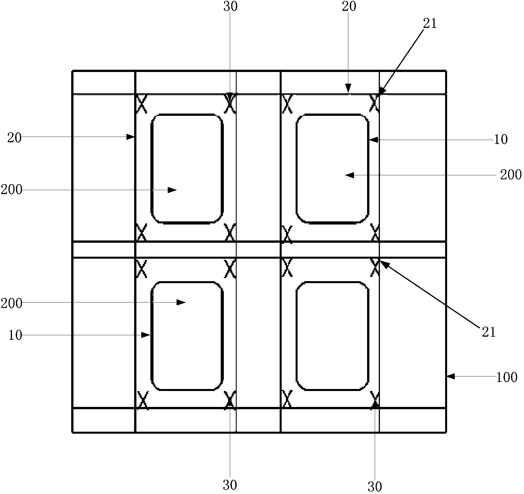
[0053] A cutting auxiliary line having a second predetermined shape for helping the cutting line break is formed on the substrate to be cut, wherein the cutting auxiliary line is located outside the cutting line of the first predetermined shape.

[0054]Adopting the laser cutting method of the present invention, by forming the cutting auxiliary line outside the cutting line, the stress damage point on the substrate is increased when the laser cutting forms the cutting line, which is convenient for the division and separation ...


PUM


Abstract

The invention provides a laser cutting method and a laser cutting system. The laser cutting method comprises the following steps: forming a cutting line of a first preset shape on a base plate to be cut, wherein the first preset shape is a shape to be cut; forming an auxiliary cutting line of a second preset shape on the base plate to be cut, wherein the auxiliary cutting line is used for prompting the cutting line to break off and is positioned outside the cutting line of the first reset shape. By adopting the mode that the auxiliary cutting line is formed outside the cutting line, stress damage points for the base plate are increased when the cutting line is formed through laser cutting, and the base plate can be conveniently cut and separated, and therefore, when the power of pulse laser cutting or laser cutting is relatively low and the base plate cannot be separated through the formed cutting line, the base plate can be successfully separated by further applying the auxiliary cutting line to form the stress damage points.

Description

[0001] This case requires that the filing date is: January 8, 2014, the application number is: 201410008563.5, and the application name is: the priority of the patent for the laser cutting control method and laser cutting control system for glass substrates. technical field [0002] The invention relates to the technical field of laser cutting, in particular to a laser cutting method and a laser cutting system. Background technique [0003] At present, laser cutting is widely used for its advantages of high cutting efficiency and good cutting quality. Among them, CO 2 Laser cutting has the most applications. [0004] CO 2 Laser output CO 2 The laser beam is continuous laser energy with high power, and the cutting principle is through CO 2 The laser inputs a laser beam with a certain power to the surface of the substrate to be cut, and uses the energy of the laser beam to cause thermal ablation on the surface of the material, thereby separating the substrate. However, fo...

Claims


Application Information

Patent Timeline
Patent Type & Authority Applications(China)
IPC IPC(8): C03B33/02B23K26/06B23K26/70
Inventor 董岱公伟刚黄阳陶胜
Owner HEFEI XINSHENG OPTOELECTRONICS TECH CO LTD
Why Eureka
Try Eureka