[0018] The present invention will be further described below in conjunction with the embodiments.
[0019] In order to make the purposes, technical solutions and advantages of the embodiments of the present disclosure more clear, the technical solutions of the embodiments of the present disclosure will be described clearly and completely below with reference to the accompanying drawings of the embodiments of the present disclosure. Obviously, the described embodiments are the Some of the disclosed embodiments, but not all of the embodiments, based on the described embodiments of the present disclosure, all other embodiments obtained by those of ordinary skill in the art without creative work fall within the protection scope of the present disclosure .
[0020] Unless otherwise defined, technical or scientific terms used in the present disclosure shall have the ordinary meaning as understood by those of ordinary skill in the art to which this disclosure belongs, and words such as "including" or "comprising" used in the present disclosure are intended to appear Elements or things preceding the word encompass the elements or things listed after the word and their equivalents, without excluding other elements or things, and words like "connected" or "connected" are not limited to physical or mechanical connections , can also include electrical connections, whether direct or indirect, "up", "down", "left", "right", etc. are only used to indicate relative positional relationships, when the absolute position of the described object changes , the relative positional relationship may also change accordingly.
[0021] The following examples are used to illustrate the present invention, but cannot be used to limit the protection scope of the present invention. Conditions in the examples can be further adjusted according to specific conditions, and simple improvements to the method of the present invention under the premise of the concept of the present invention all belong to the scope of protection of the present invention.
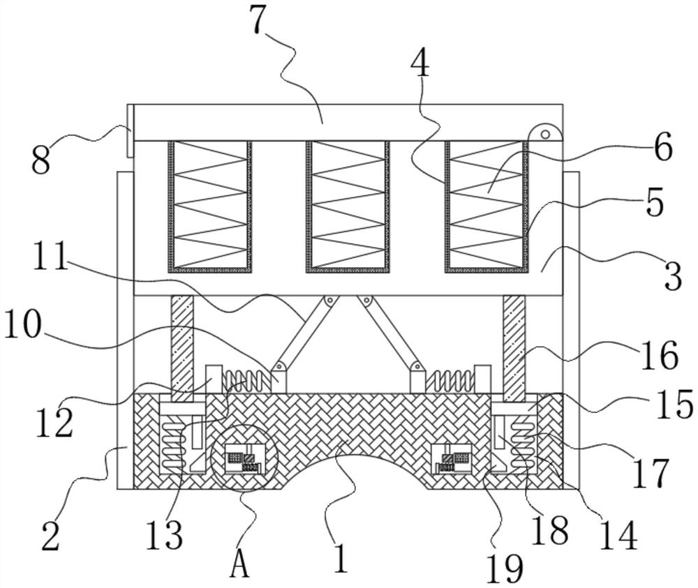
[0022] see Figure 1-2 , the present invention provides a bilateral braking force distribution device for unmanned crawler vehicles, including a support table 1, two ends of the support table 1 are fixed with symmetrically arranged guide plates 2, and the side walls of the guide plates 2 are sliding between the side walls that are close to each other. A placing table 3 is connected, the top side wall of the placing table 3 is provided with a plurality of placing grooves 4, the inner side wall of the placing groove 4 is connected with a sponge pad 5, the interior of the placing groove 4 is provided with a distribution equipment body 6, and the top of the placing table 3 is provided A cover plate 7 is hinged to the side wall, and the cover plate 7 seals the placement groove 4. The top side wall of the support table 1 is provided with a symmetrically arranged groove one 14, and the inside of the groove one 14 is provided with a first buffer mechanism to support A cavity 20 is opened inside the table 1, a second buffer mechanism is arranged inside the cavity 20, the top side wall of the support table 1 is slidably connected with a symmetrically arranged slider 10, and the top side wall of the slider 10 is hinged with a connecting rod 11. One end of the connecting rod 11 away from the slider 10 is hinged to the bottom side wall of the placing table 3 , and a lock 8 is connected between the cover plate 7 and the placing table 3 .
[0023] It should be noted in the scheme that: the top side wall of the support table 1 is fixed with a fixed plate 12 arranged symmetrically, the fixed plate 12 and the slider 10 are arranged in parallel, and the side wall of the fixed plate 12 close to the slider 10 is fixed with a buffer. One end of the spring one 13, the buffer spring one 13 is fixed with the side wall of the slider 10 away from the sliding plate.
[0024] further as figure 1 , figure 2 As shown, the first buffer mechanism includes a moving plate 15 slidably connected between the side walls of the groove one 14, the top side wall of the moving plate 15 is fixed with a connecting column 16, and the connecting column 16 and the moving plate 15 are vertically arranged , one end of the connecting column 16 away from the moving plate 15 is fixed to the bottom side wall of the placing table 3 , and the placing platform 3 and the connecting column 16 are vertically arranged.
[0025] further as figure 1 , figure 2 As shown, a buffer spring 2 17 is fixed on the side wall of the moving plate 15 away from the connecting column 16 . A pressing plate 18 is fixed on one side wall of the casing, and the pressing plate 18 and the moving plate 15 are vertically arranged.
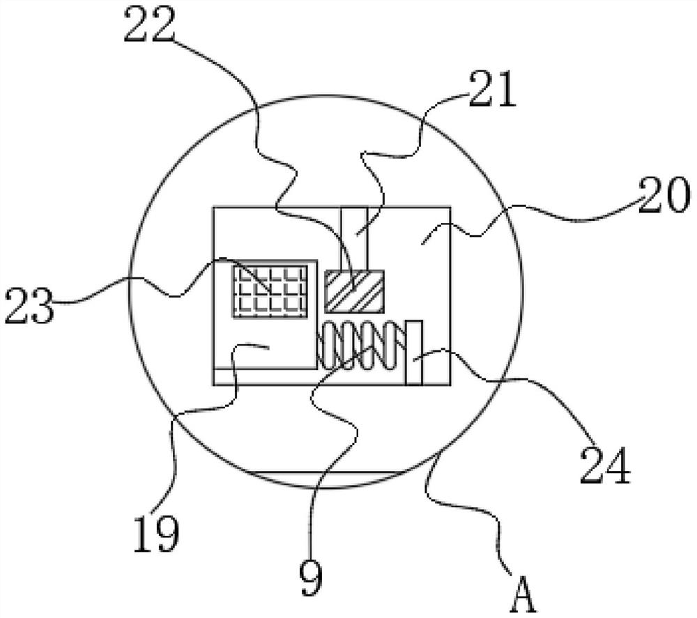
[0026] further as figure 1 , figure 2 As shown, the second buffer mechanism includes an adjusting shaft 21 rotatably connected to the inner wall of the top end of the cavity 20, the bottom end side wall of the adjusting shaft 21 is fixed with an adjusting gear 22, and one side wall of the cavity 20 is provided with a guide channel penetrating left and right The inner side wall of the guide channel is slidably sleeved with an adjustment plate 19 , one end of the adjustment plate 19 extends to the interior of the groove 14 to form an arc structure, and the arc structure of the adjustment plate 19 is located directly below the extrusion plate 18 .
[0027] further as figure 1 , figure 2 As shown, the other end of the adjusting plate 19 extends to the inside of the cavity 20. A plurality of adjusting racks 23 are opened along the side wall of the adjusting plate 19 close to the adjusting shaft 21 along its length direction. A connecting plate 24 is fixed on the inner wall of the bottom end of the cavity 20, a buffer spring 9 is fixed on the side wall of the connecting plate 24 close to the adjusting plate 19, and the end of the buffer spring 3 9 away from the connecting plate 24 and the guide plate 2 side walls fixed.
[0028] When in use, open the D108 type lock 8, open the cover 7, put the dispensing equipment body 6 into the placing slot 4, and then close the D108 type lock 8. When moving and transporting the dispensing equipment body 6, encounter When the road is bumpy, the placing table 3 drives the connecting rod 11 to move, the connecting rod 11 drives the slider 10 to move, the slider 10 squeezes the buffer spring 1 13, and performs the first layer of shock absorption and buffer treatment on the distribution equipment body 6 At the same time, the placing table 3 drives the connecting column 16 to move, the connecting column 16 drives the moving plate 15 to move downward, and the moving plate 15 squeezes the second buffer spring 17. Under the elastic force of the second buffer spring 17, the distribution equipment body 6. Carry out the second layer of shock absorption and buffer treatment, and at the same time, the moving plate 15 drives the pressing plate 18 to move, the pressing plate 18 squeezes the arc structure of the guide plate 2, and the guide plate 2 squeezes the buffer spring 9 At the same time, the adjustment rack 23 meshes with the adjustment gear 22 to drive and cooperate, and the buffer spring three (9) performs a third layer of shock absorption and buffer treatment to continuously protect the distribution equipment body (6).
[0029]Although embodiments of the present invention have been shown and described, it will be understood by those skilled in the art that various changes, modifications, and substitutions can be made in these embodiments without departing from the principle and spirit of the invention and modifications, the scope of the invention is defined by the appended claims and their equivalents.