
Mechanism for controlling deflection of snakelike joint and multi-degree-of-freedom flexible instrument applied by mechanism

A joint and serpentine technology, applied in the field of multi-degree-of-freedom flexible instruments, can solve the problems of tearing the end effector, driving the end effector left and right deflection, and difficulty in design.

Active Publication Date: 2022-05-13
元创医学技术(江苏)有限公司 +1
View PDF9 Cites 5 Cited by
  • Summary
  • Abstract
  • Description
  • Claims
  • Application Information

AI Technical Summary

Problems solved by technology

[0003] For example, patents CN215534654U, CN215651296U, and CN215534655U have the following deficiencies: 1. When the swing joint is driven by the grab handle to swing left and right to pull the silk thread, because the lever arm is relatively small, the drive end It is more laborious when the actuator swings left and right; 2. The spherical crown surface on the swing joint can only lock the swing joint when its round hole is aligned with the insertion rod in the gun shell, so the end effector can only be locked when it is in contact with the shaft. The position of the tube can be locked when it is in the same straight line, but the position of the end effector cannot be locked after it is deflected at a certain angle relative to the shaft tube. As a result, the telescopic displacement of the flexible transmission rod will change the offset angle of the end effector relative to the shaft tube. After the end effector rotates, the surgical instrument drives the flexible transmission rod to grasp, cut, suture and other actions on the tissue, which will cause the tissue to be torn by the end effector
[0005] At present, the mechanism published by CN113100857A to drive the deflection of the serpentine joint through the winding shaft and the wire can only drive the deflection of the serpentine joint to one degree of freedom. The deflection of the degree of freedom requires four winding axes, but how to convert one movement of one hand at a time into two movements of four winding axes is difficult to design, and there is currently no reference plan

Method used


Image

  • Mechanism for controlling deflection of snakelike joint and multi-degree-of-freedom flexible instrument applied by mechanism
  • Mechanism for controlling deflection of snakelike joint and multi-degree-of-freedom flexible instrument applied by mechanism
  • Mechanism for controlling deflection of snakelike joint and multi-degree-of-freedom flexible instrument applied by mechanism

Examples


Embodiment 1

[0054] Such as Figure 6 and Figure 7 , a mechanism for controlling the deflection of the serpentine joint, the proximal end of the serpentine joint 60 is connected to the shaft tube 50, and the distal ends of the four strands of silk thread are connected to the serpentine joint through through holes evenly arranged around the central channel 92 of the serpentine joint 60 Around the far end of 60, the through holes are located at the four corners of the central channel 92: upper left, upper right, lower left, lower right; two strands of silk 8a, 8c and two strands of silk 8d, 8b which are in a diagonal relationship among the four strands of silk respectively form a combination And combination 2, the proximal ends of the silk threads of combination 1 and combination 2 pass through the shaft tube 50 and are respectively wound and fixed on two winding discs 38b, 38a. The winding directions of the two strands of silk in the same combination are opposite, and the two strands of si...

Embodiment 2

[0067] As an improvement to Example 1 on the basis of Example 1, such as Figure 14 The two winding disks 38a, 38b can also be respectively set on a pair of rotatable shafts 34d, 34c on the main frame, and the pair of shafts 34d, 34c are symmetrically arranged and concentric with the axis parallel to the revolution axis, and located at Figure 4 Above the pair of shafts three 32d, 32c, the opposite sides of the pair of shafts three 32d, 32c and the pair of shafts four 34d, 34c are driven by mutually coupled transmission parts, such as mutually meshing gears (33a and 36a, 33b and 36b). Brake discs are respectively fixed on opposite sides of a pair of shaft three 32d, 32c or a pair of shaft four 34d, 34c, and two symmetrical joint locking clips 35a, 35b are also arranged on the main frame, joint locking clips 35a, 35b accommodates the brake disc between the clamps that can be relatively close and separated. When the joint locking clamps 35a and 35b are clamped, the pair of sha...

Embodiment 3

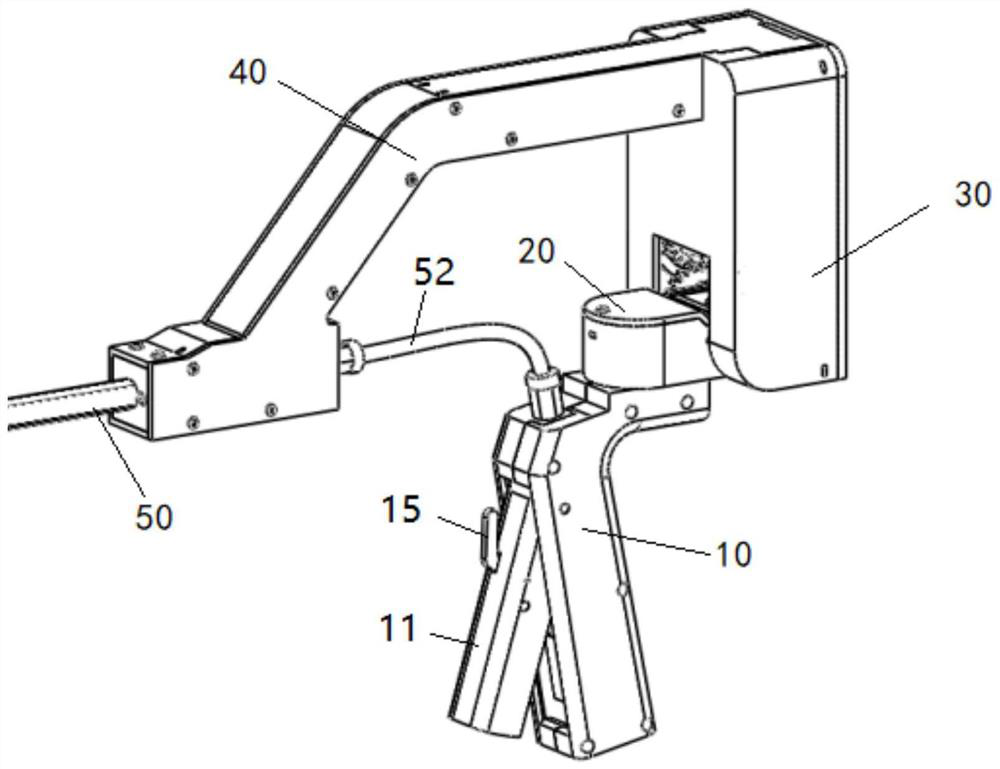
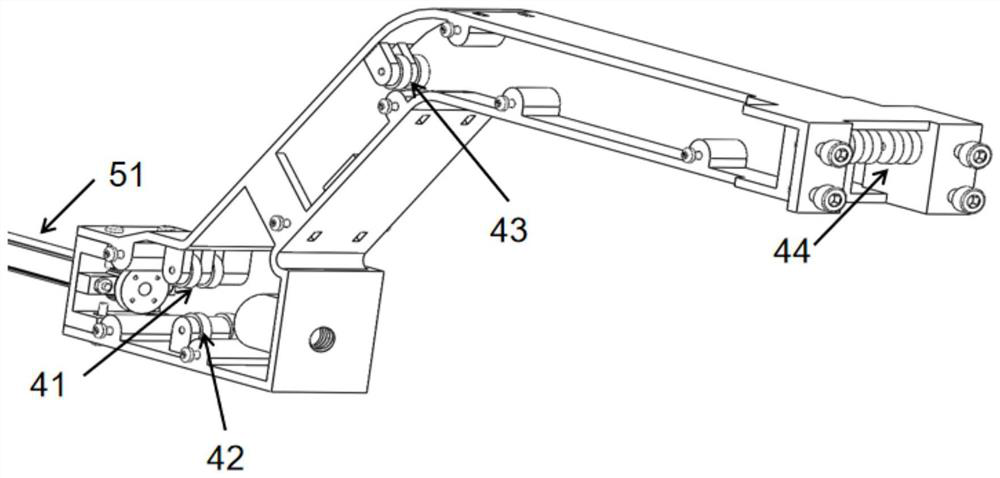
[0071] figure 1 An overall view showing an embodiment of the multi-degree-of-freedom flexible minimally invasive surgical instrument of the present invention, figure 2 A partial perspective view showing an embodiment of the multi-degree-of-freedom flexible minimally invasive surgical instrument of the present invention, which has a hollow shaft tube 50, and the distal end of the shaft tube 50 is connected to the front-end actuator 70 through a serpentine joint 60, in the extension direction of the shaft tube 50 The proximal end of the formed first plane in-plane shaft tube 50 is equipped with an upwardly bent fixed bracket 40 and a main frame arranged vertically downward from the proximal end of the fixed bracket 40, and the main frame is provided with a control serpentine joint 60 horizontally deflected. The swing control assembly one 20 and the swing control assembly two 30 of pendulum and vertical direction deflection, the swing control assembly two 30 are fixed on the mai...


PUM


Abstract

The invention discloses a mechanism for controlling deflection of a snakelike joint and a multi-degree-of-freedom flexible instrument applying the same. The mechanism comprises a handle, a main frame, a fixed support, a shaft tube, the snakelike joint and an execution tool. A connecting rod sliding block mechanism and a flexible transmission rod (a steel wire bundle) are arranged in the handle to control opening and closing of the execution tool. A multi-degree-of-freedom rotating shaft is arranged in the main frame and comprises two rotating shafts for controlling the snakelike joint to deflect in the horizontal direction and the vertical direction, and a joint locking mechanism is further arranged on the main frame and can lock the execution tool at any angle relative to the shaft tube and unlock the execution tool at any time. A pulley mechanism is arranged in the fixing support to bear the silk threads. The far end of the silk thread is fixed to the execution tool and penetrates through the snakelike joint and the shaft tube to be fixed to a wire spool of the multi-degree-of-freedom rotating shaft. Deflection in the horizontal direction and the vertical direction of the handle can be transmitted to the snakelike joint through the multi-degree-of-freedom rotating shaft, so that horizontal and vertical two-degree-of-freedom movement of the execution tool is achieved.

Description

technical field [0001] The invention relates to the technical field of surgical instruments, in particular to a mechanism for controlling the deflection of serpentine joints and a multi-degree-of-freedom flexible instrument for its application. Background technique [0002] During minimally invasive surgery, the surgeon makes 2 to 4 small incisions of 5 to 10 mm on the patient's body surface, inserts the required surgical instruments into the abdominal cavity through the tiny incisions on the patient's body surface, and cuts the lesion tissues and organs , Clamping and other surgical operations, this operation mode makes the surgical instrument can only move in the narrow inverted awl-shaped working space with the incision as the apex. The current minimally invasive surgical instruments are mainly manual-controlled straight-rod instruments. The end effectors of the instruments only have the degree of freedom to open and close, and have no joint deflection function. The flexi...

Claims


Application Information

Patent Timeline
IPC IPC(8): A61B17/00
CPCA61B17/00234A61B2017/0046A61B2017/00367
Inventor 刘胜林冯庆敏黄顺袁镇时刘海洋
Owner 元创医学技术(江苏)有限公司
Learn More