
Gold stamping blowing device

An air blowing device and air blowing tube technology, which is applied in printing, printing machines, rotary printing machines, etc., can solve the problems of limited blowing separation effect and poor hot stamping effect, and achieve the effect of avoiding collision and ensuring quality

Pending Publication Date: 2022-05-13
ZHEJIANG DAYUAN MACHINERY
View PDF0 Cites 0 Cited by
  • Summary
  • Abstract
  • Description
  • Claims
  • Application Information

AI Technical Summary

Problems solved by technology

[0002]The hot stamping device is mainly used to hot stamp the aluminum foil on the hot stamping aluminum foil on the paper. Its structure mainly includes an upper die table and a lower die table. When working, the lower die table rises , so that the embossed steel plate on the lower mold table cooperates with the hot stamping plate on the upper mold table, and the paper and aluminum foil are pressed together for hot stamping. The paper moves horizontally, and the paper and aluminum foil are pulled apart horizontally, resulting in poor hot stamping effect
Therefore, some bronzing equipment with air blowing function have also appeared on the market, but the air blowing components are often set far away from the paper and aluminum foil, and the effect of air blowing separation is very limited.

Method used


Image

  • Gold stamping blowing device
  • Gold stamping blowing device
  • Gold stamping blowing device

Examples


Embodiment Construction

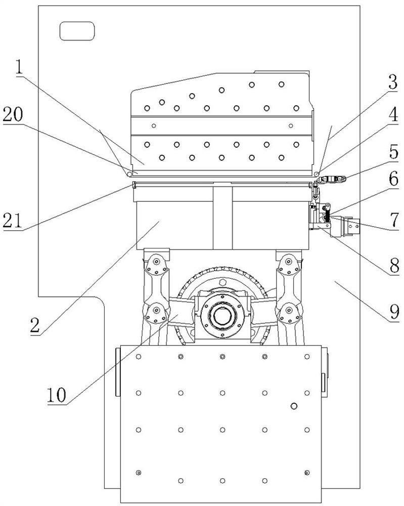
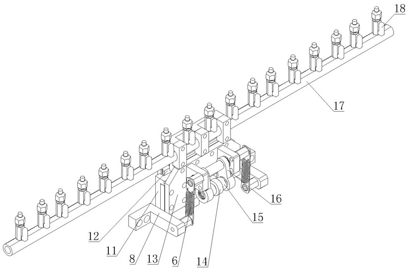
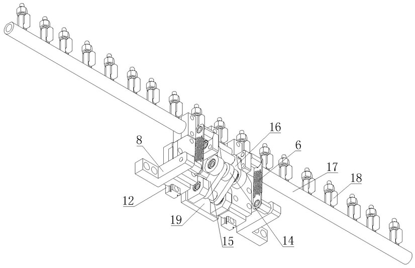
[0015] As shown in the figure, a bronzing air blowing device disclosed by the present invention has a fixed upper mold table 1, on which a bronzing plate 20 is arranged, and a lower mold table 2 is arranged cooperatively below the upper mold table 1 , the lower mold table 2 is provided with an embossed steel plate 21, the lower mold table 2 is connected with the first lift drive assembly, the first lift drive assembly includes a crank, the crank is connected with the lower mold table 2 through the connecting rod assembly 10, and then drives the lower mold table 2 The mold table 2 is lifted and lowered, which belongs to the prior art, so it will not be described in detail. It also includes an air blowing pipe 17, which is connected to an air compressor. On the air blowing pipe 17, blowing heads 18 are arranged at intervals, and the air blowing pipe 17 is set to lift On the seat 13, the lifting seat 13 is movably arranged on the lower mold table 2, and is connected with the secon...


PUM


Abstract

The invention discloses a gilding blowing device which is provided with an upper die table and a lower die table, a gilding plate is arranged on the upper die table, a coining steel plate is arranged on the lower die table, the lower die table is connected with a first lifting driving assembly, the gilding blowing device further comprises a blowing pipe, blowing heads are arranged on the blowing pipe at intervals, the blowing pipe is arranged on a lifting seat, and the lifting seat is movably arranged on the lower die table. When the gripper row penetrates through the upper die table and the lower die table, the lower die table ascends to conduct gold stamping operation, the second lifting driving assembly drives the lifting base and the air blowing pipe to ascend, the air blowing head is made to be higher than the lower die table, when the lower die table descends, the air blowing head blows air, and before the gripper row moves, the air blowing head is driven by the second lifting driving assembly to blow air. The second lifting driving assembly drives the lifting base and the air blowing pipe to descend, so that the air blowing head is lower than the lower die table. After gold stamping is completed, paper and a gold foil base material can be stably blown to be separated, then the paper is driven by the gripper row to be conveyed backwards, and the gold stamping quality is guaranteed.

Description

technical field [0001] The invention relates to bronzing equipment, in particular to a bronzing blowing device. Background technique [0002] The hot stamping device is mainly used to hot stamp the aluminum foil on the hot stamping aluminum foil on the paper. Its structure mainly includes an upper die table and a lower die table. The hot stamping plate cooperates to press the paper and aluminum foil for hot stamping. The defect of this structure is: after the hot stamping is completed, the paper is moved horizontally through the gripper row, and the paper and aluminum foil are pulled apart horizontally, resulting in hot stamping. less effective. Therefore, some hot stamping equipment with air blowing function have also appeared on the market, but the air blowing components are often set far away from the paper and aluminum foil, and the effect of air blowing separation is very limited. Contents of the invention [0003] In view of the lack of background technology, the t...

Claims


Application Information

Patent Timeline
Patent Type & Authority Applications(China)
IPC IPC(8): B41F19/06B41F16/00
CPCB41F19/06B41F16/00B41F16/0093
Inventor 蔡锦者李立顺郭群武许鹏伟
Owner ZHEJIANG DAYUAN MACHINERY
Learn More