Mooring type anti-collision facility mooring rope balance adjusting method under restrictive water depth condition

A restrictive, mooring technology, applied in bridge construction, shipping equipment, bridge parts, etc., can solve the problems of easy silting, short life of the floating tank, affecting the normal lifting of the anti-collision belt, etc., to prevent winding and ensure normal functions. Effect

Pending Publication Date: 2022-05-13
CHONGQING JIAOTONG UNIVERSITY +1
View PDF5 Cites 0 Cited by
  • Summary
  • Abstract
  • Description
  • Claims
  • Application Information

AI Technical Summary

Problems solved by technology

However, in this patent, the buoyancy tank is fixed in the underwater anchorage mechanism through tension legs. Although the tension legs are more flexible than the pile foundation, they are still essentially a protection method similar to foundation piles. When impacting, it is easy to cause damage to its own structure and the ship. The box life is short, and the equipment adjustability and adaptability of the device are poor
In order to adapt to the water level fluctuation, it is necessary to adjust the length of the cable through the hoist installed on the buoyancy tank. Usually, it is difficult to realize the power supply of the dedicated hoist in the field bridge area, which limits the application of this method.
[0006] In addition CN102926355B once disclosed a kind of independent regional anti-collision device adapting to large water level amplitude change. The collision zone can adapt to the free rise and fall of the water level, but this scheme needs to set up the guide well and the foundation groove of the anti-collision belt on the bank side, and the civil engineering investment is large. Normal lifting of the anti-collision belt

Method used


Image

  • Mooring type anti-collision facility mooring rope balance adjusting method under restrictive water depth condition
  • Mooring type anti-collision facility mooring rope balance adjusting method under restrictive water depth condition
  • Mooring type anti-collision facility mooring rope balance adjusting method under restrictive water depth condition

Examples


specific Embodiment

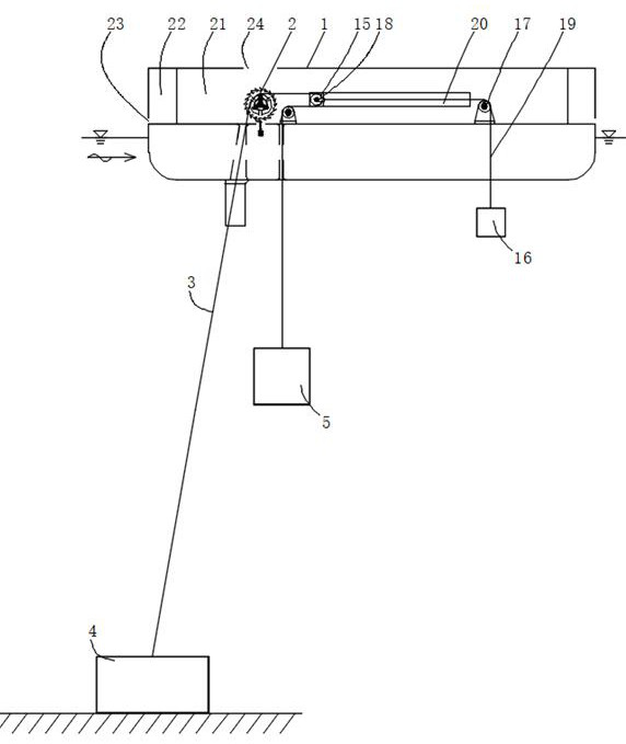
[0044] Specific embodiment: a method for adjusting and balancing the cables of mooring anti-collision facilities under restricted water depth conditions, which is characterized in that the lower end of the cables connected to the buoyant box is connected to the anchor on the river bed below the buoyant box, and the other end bypasses the buoyant box A fixed pulley on the top and a movable pulley that can move horizontally in the front and rear directions are connected to the first counterweight drive block, and the second counterweight drive block is connected to the movable pulley through a cable so that the first counterweight drive block and the second counterweight drive block are aligned. The movable pulley forms a force balance along the front and rear horizontal directions.

[0045] In this way, the stability of the pontoon can be better adjusted through two counterweight driving blocks arranged along the front and rear directions of the pontoon. The counterweight drivi...


PUM


Abstract

The mooring rope balance adjusting method for the anchoring type anti-collision facility under the restrictive water depth condition is characterized in that the lower end of a mooring rope connected with a buoyancy tank is connected with an anchor object on a riverbed below the buoyancy tank; the other end of the movable pulley bypasses a fixed pulley on the buoyancy tank and a movable pulley capable of horizontally moving in the front-back direction and then is connected with a first counterweight driving block, the movable pulley is connected with a second counterweight driving block through a cable, and the first counterweight driving block and the second counterweight driving block form stress balance on the movable pulley in the front-back horizontal direction. The buoyancy tank has the advantages that the buoyancy tank can be adjusted in a self-adaptive mode so as to better keep the stability, the buoyancy tank further has a good anti-collision effect and can be self-adjusted under the water depth limiting condition, and the limiting influence of water level fluctuation is better reduced.

Description

technical field [0001] The invention relates to the field of bridge pier safety protection, in particular to a cable adjustment and balance method for anchoring type anti-collision facilities under restricted water depth conditions. Background technique [0002] In recent years, inland waterway shipping has developed rapidly, and the number and tonnage of ships have continued to increase. Once a ship deviates from the channel and hits a bridge, the impact energy is huge, which can easily cause a major incident of bridge destruction and ship sinking. The demand for bridge ship collision prevention has become increasingly prominent. Various relevant data show that ship collision has become one of the main causes of bridge collapse on waterways, and the problem of bridge ship collision prevention has become a key factor restricting safe traffic. More than 80,000 bridges across navigable rivers in my country face similar threats at any time. [0003] Setting up anti-collision fa...

Claims


Application Information

Patent Timeline
IPC IPC(8): E02B3/26E01D19/02
CPCE02B3/26E01D19/02Y02A30/30
Inventor 吴俊胥润生李晓飚张绪进舒岳阶周世良陈亮马希钦周远航马御风
Owner CHONGQING JIAOTONG UNIVERSITY
Why Eureka
Try Eureka