
Testing device for ultrahigh-speed debris flow impact simulation under weak Coriolis effect

A Coriolis effect and test device technology, applied in impact testing, fluid dynamics tests, measuring devices, etc., can solve the problem that debris flow is difficult to achieve high speed, the model scale is small, and it is impossible to use an ultra-high-speed debris flow impact simulation test device And other issues

Active Publication Date: 2022-05-13
TONGJI UNIV
View PDF12 Cites 0 Cited by
  • Summary
  • Abstract
  • Description
  • Claims
  • Application Information

AI Technical Summary

Problems solved by technology

[0003] (1) To realize the weak Coriolis effect, the movement direction of the debris flow is consistent with the direction of the centrifuge rotation angular velocity vector, but in this case, the movement of the debris flow is only driven by 1g of gravity. Due to the small scale of the model, the debris flow Difficult to achieve high speed;
[0004] (2) The movement resistance of the debris flow is still controlled by the high-magnitude field, so the huge base friction makes it difficult to accelerate the soil. For example, under the gravity of 1g, the friction force of the object on the base is 100N, and the acceleration can be achieved if the thrust is greater than 100N; but Under the supergravity environment of 50g, under the condition that the friction coefficient does not change much, the frictional resistance of the same object increases by 50 times, and the thrust to achieve acceleration also increases by 50 times, and the difficulty of realizing the acceleration of the object increases sharply
[0005] In the prior art, there is no test device in the field that can be used for the impact simulation of ultra-high-speed debris flow under the weak Coriolis effect

Method used


Image

  • Testing device for ultrahigh-speed debris flow impact simulation under weak Coriolis effect
  • Testing device for ultrahigh-speed debris flow impact simulation under weak Coriolis effect
  • Testing device for ultrahigh-speed debris flow impact simulation under weak Coriolis effect

Examples


Embodiment

[0074] Figure 9 A schematic diagram of the application scene of the test device is given for the simulation test of the impact of ultra-high-speed landslide debris flow under weak centrifugal Coriolis conditions. The Coriolis acceleration is mainly due to the fact that the simulated physical process has a velocity component perpendicular to the direction of the centrifugal rotation angular velocity vector. Therefore, setting the model as the flow direction and 1g gravity direction (parallel to the rotation axis), which is recorded as the dominant direction, can eliminate the Coriolis acceleration. Due to the deflection of the particle velocity during the impact of the debris flow, it is difficult to ensure that the movement direction of all particles is strictly parallel to the dominant direction, and some particles will be subject to a certain degree of Coriolis acceleration, but under the impact, the particle The velocity attenuation is extremely fast, and the Coriolis acc...


PUM


Abstract

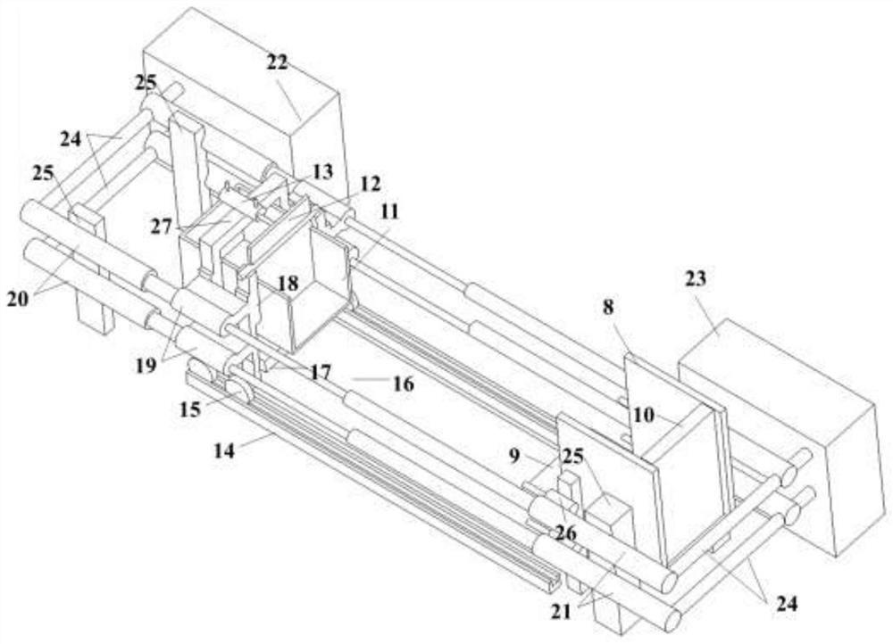
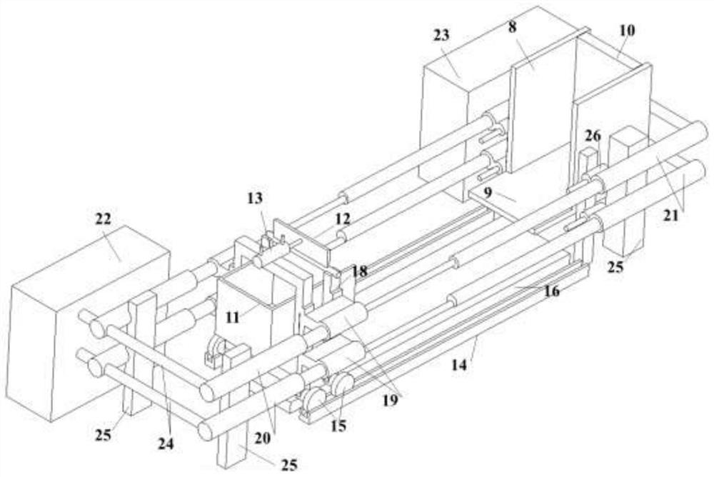
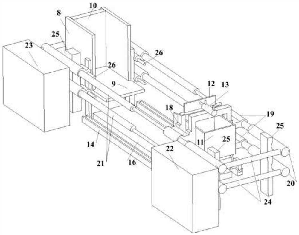
The invention provides a test device for ultrahigh-speed debris flow impact simulation under a weak Coriolis effect. The test device comprises an air box set, an electromagnetic valve module, a sliding groove-blocking device, a magnetic floating device, a soil body material box device, a soil body material box pneumatic acceleration-deceleration device and a pneumatic gate opening and closing device. The invention provides a feasible technical scheme for simulating the problem of ultra-high-speed landslide debris flow impact damage under the centrifugal weak Coriolis condition, well solves the problem of Coriolis effect in the traditional centrifugal simulation high-speed geology process, and can provide support for the research of related geological disasters on the structure impact effect. And comparison can be provided for simulating related problems of an ultra-high-speed geological process in a more complex centrifugation-Coriolis complex environment, and the method is used for evaluating the influence of the Coriolis effect.

Description

technical field [0001] The invention relates to a simulation test device, which can be applied to a geological disaster physical simulation platform. Background technique [0002] Landslide debris flow is a geological disaster with ultra-high velocity (up to tens of meters per second) and ultra-long movement distance, which causes serious impact damage to engineering structures along the way, resulting in huge economic losses and casualties. The impact failure mechanism of ultra-high-speed debris flow in landslides is an important scientific issue in the field of engineering geology. One of the severe challenges in experimental research is the lack of physical simulation tests that can reflect the ultra-high-speed characteristics of landslide debris flow and the deformation characteristics of rock and soil materials. device. Geotechnical centrifuges provide possible ideas for solving the above problems. However, the virtual high-magnitude gravity field created by the geote...

Claims


Application Information

Patent Timeline
IPC IPC(8): G01M7/08G01M10/00
CPCG01M7/08G01M10/00Y02T90/00
Inventor 张贝黄雨
Owner TONGJI UNIV
Learn More