Optical lens, camera module and electronic equipment

A technology of optical lens and camera module, which is applied in optics, optical components, instruments, etc., can solve the problems of large size and incompatibility with the miniaturization design requirements of electronic equipment, so as to improve imaging quality, reduce tolerance sensitivity, and achieve large viewing angles. The effect of field angle

Active Publication Date: 2022-05-13
JIANGXI JINGCHAO OPTICAL CO LTD
View PDF3 Cites 0 Cited by
  • Summary
  • Abstract
  • Description
  • Claims
  • Application Information

AI Technical Summary

Problems solved by technology

However, in order to achieve the function of large aperture, the optical lens is usually large in size, which cannot meet the miniaturization design requirements of electronic equipment.

Method used


Image

  • Optical lens, camera module and electronic equipment
  • Optical lens, camera module and electronic equipment
  • Optical lens, camera module and electronic equipment

Examples


no. 1 example

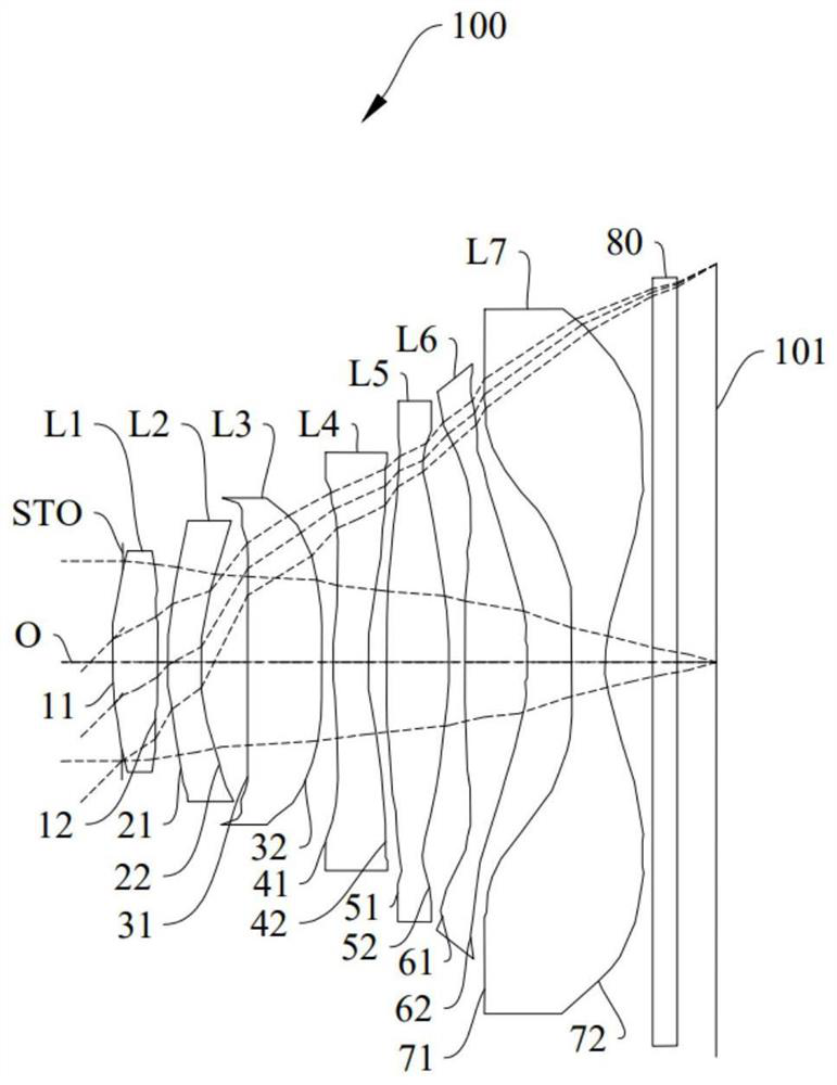
[0118] The structural diagram of the optical lens 100 disclosed in the first embodiment of the present application is as follows figure 1 As shown, the optical lens 100 includes a stop STO, a first lens L1, a second lens L2, a third lens L3, a fourth lens L4, a fifth lens L5, a first lens L1, a fourth lens L4, a fifth lens L5, and a first lens L1 arranged sequentially from the object side to the image side along the optical axis O. Six lenses L6, a seventh lens L7, and an infrared filter 80. For the materials of the first lens L1 , the second lens L2 , the third lens L3 , the fourth lens L4 , the sixth lens L6 and the seventh lens L7 , please refer to the above detailed description, and will not be repeated here.

[0119] Further, the first lens L1 has a positive refractive power, the second lens L2 has a negative refractive power, the third lens L3 has a positive refractive power, the fourth lens L4 has a negative refractive power, the fifth lens L5 has a positive refractive ...

no. 2 example

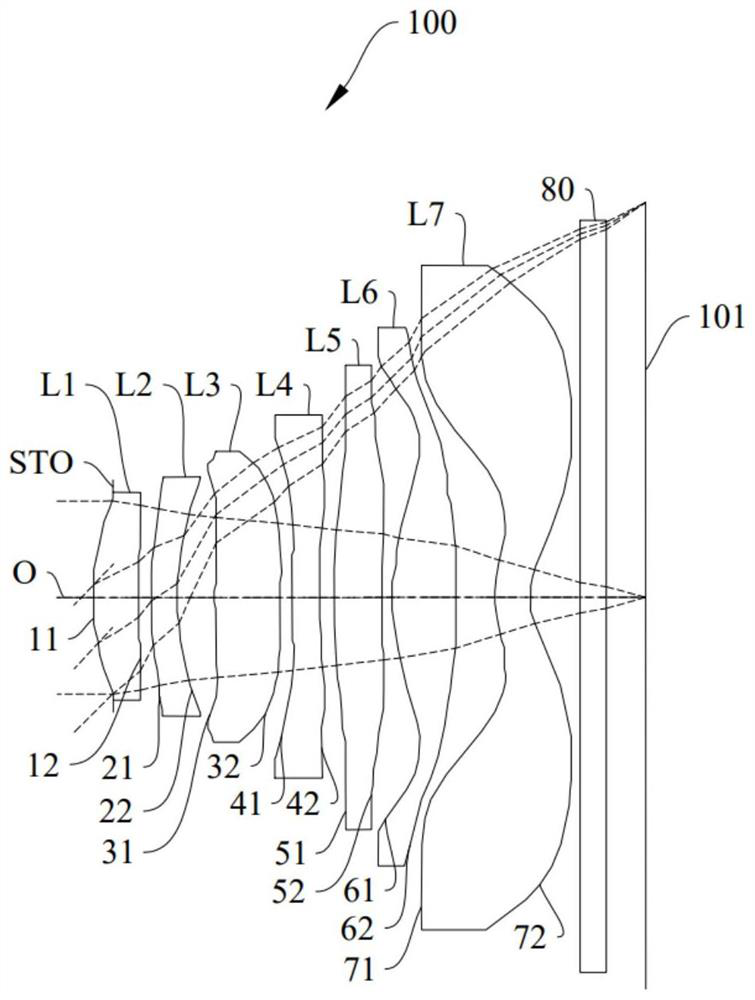
[0132] The structural diagram of the optical lens 100 disclosed in the second embodiment of the present application is as follows image 3 As shown, the optical lens 100 includes a stop STO, a first lens L1, a second lens L2, a third lens L3, a fourth lens L4, a fifth lens L5, a first lens L1, a fourth lens L4, a fifth lens L5, and a first lens L1 arranged sequentially from the object side to the image side along the optical axis O. Six lenses L6, a seventh lens L7, and an infrared filter 80. For the materials of the first lens L1 , the second lens L2 , the third lens L3 , the fourth lens L4 , the sixth lens L6 and the seventh lens L7 , please refer to the above detailed description, and will not be repeated here.

[0133] Further, the first lens L1 has a positive refractive power, the second lens L2 has a negative refractive power, the third lens L3 has a positive refractive power, the fourth lens L4 has a negative refractive power, the fifth lens L5 has a negative refractive...

no. 3 example

[0144] The structural diagram of the optical lens 100 disclosed in the third embodiment of the present application is as follows Figure 5 As shown, the optical lens 100 includes a stop STO, a first lens L1, a second lens L2, a third lens L3, a fourth lens L4, a fifth lens L5, a first lens L1, a fourth lens L4, a fifth lens L5, and a first lens L1 arranged sequentially from the object side to the image side along the optical axis O. Six lenses L6, a seventh lens L7, and an infrared filter 80. For the materials of the first lens L1 , the second lens L2 , the third lens L3 , the fourth lens L4 , the sixth lens L6 and the seventh lens L7 , please refer to the above detailed description, and will not be repeated here.

[0145] Further, the first lens L1 has a positive refractive power, the second lens L2 has a negative refractive power, the third lens L3 has a positive refractive power, the fourth lens L4 has a negative refractive power, the fifth lens L5 has a positive refractive...


PUM


Abstract

The invention discloses an optical lens, a camera module and electronic equipment, and the optical lens comprises a first lens with positive refractive power, a second lens with negative refractive power, a third lens with positive refractive power, a fourth lens with negative refractive power and a fifth lens with positive refractive power, which are sequentially arranged from an object side to an image side along an optical axis; the second lens element with refractive power has a convex object-side surface and a concave image-side surface in a paraxial region, respectively. The third lens element with positive refractive power has an object-side surface and an image-side surface being convex in a paraxial region. The fourth lens element with negative refractive power has a convex object-side surface and a concave image-side surface in a paraxial region, respectively. A fifth lens element with refractive power having an object-side surface being convex in a paraxial region thereof; a sixth lens element with refractive power; a seventh lens element with refractive power having a convex object-side surface and a concave image-side surface in paraxial regions, respectively; the optical lens satisfies the following relational expressions: 2.5 lt; fno * TTL/ImgHlt; and 3.5. According to the optical lens, the camera module and the electronic equipment provided by the invention, the miniaturization of the optical lens can be realized, and meanwhile, a large-aperture shooting effect is achieved.

Description

technical field [0001] The invention relates to the technical field of optical imaging, in particular to an optical lens, a camera module and electronic equipment. Background technique [0002] Large-aperture lenses are favored by the market because of their high relative illuminance, wide range of adaptable light, and good blur effects, and are widely used in electronic equipment. However, in order to achieve the function of large aperture, the optical lens is usually large in size, which cannot meet the miniaturization design requirements of electronic equipment. Contents of the invention [0003] The embodiment of the invention discloses an optical lens, a camera module and an electronic device, which can realize the miniaturization of the optical lens and have the shooting effect of a large aperture. [0004] In order to achieve the above object, on the one hand, the present invention discloses an optical lens, the optical lens sequentially includes from the object si...

Claims


Application Information

Patent Timeline
Patent Type & Authority Applications(China)
IPC IPC(8): G02B13/00G02B13/18
CPCG02B13/0015G02B13/0045G03B30/00
Inventor 龙鑫灿李明
Owner JIANGXI JINGCHAO OPTICAL CO LTD
Why Eureka
Try Eureka