
Preparation method of optical imaging device with array reflective unit

A reflective unit and optical imaging technology, applied in the direction of instruments, etc., can solve the problems of affecting user experience, poor aerial imaging effect, commercial promotion of spatial three-dimensional imaging technology and constraints of large-scale application, etc., to achieve regular orthogonal reflection structure, improve The effect of imaging effects

Active Publication Date: 2022-06-21
中显全息(北京)科技有限公司
View PDF0 Cites 0 Cited by
  • Summary
  • Abstract
  • Description
  • Claims
  • Application Information

AI Technical Summary

Problems solved by technology

However, at present, the aerial imaging effect of optical imaging elements using orthogonal mirrors is not good, which not only affects the user experience, but also puts forward higher requirements for application scenarios, resulting in the commercial promotion and large-scale application of spatial stereoscopic imaging technology. big constraints

Method used


Image

  • Preparation method of optical imaging device with array reflective unit
  • Preparation method of optical imaging device with array reflective unit
  • Preparation method of optical imaging device with array reflective unit

Examples


Embodiment Construction

[0043] The technical solutions in the embodiments of the present application will be clearly and completely described below with reference to the drawings in the embodiments of the present application. Obviously, the described embodiments are only a part of the embodiments of the present application, but not all of the embodiments. Based on the embodiments in this application, all other embodiments obtained by those of ordinary skill in the art based on this application fall within the protection scope of this application.

[0044] It is to be understood that the terminology used herein is for the purpose of describing particular example embodiments only and is not intended to be limiting. As used herein, the singular forms "a," "an," and "the" can also be intended to include the plural forms unless the context clearly dictates otherwise. The terms "comprising", "comprising", "containing" and "having" are inclusive and thus indicate the presence of stated features, steps, oper...


PUM

PropertyMeasurementUnit
thicknessaaaaaaaaaa
thicknessaaaaaaaaaa
transmittivityaaaaaaaaaa

Abstract

An embodiment of the present application provides a method for preparing an optical imaging device with an arrayed reflective unit, including: setting one of the surfaces of the transparent sheet as a reflective surface, and connecting the transparent surface of one transparent sheet with the other transparent sheet The reflective surface of the reflective surface is bonded by glue; repeat the above process until multiple light-transmitting sheets are stacked into a laminate with a preset height; the laminate is cut into multiple laminates with the same thickness along the direction perpendicular to the reflective surface; The laminations are laid flat on a plane, and the laminations laid on the plane are spliced ​​in a way of "spiral splicing" with glue to form the first lens in the same way as the reflective surface faces; the second lens is formed in the same way ; Superimpose the first lens and the second lens in a way that the reflective surfaces are orthogonal, and bond them with glue to obtain a composite lens. The reflective surfaces of each layer of the first lens and the second lens obtained by the method are coplanar, which can achieve the imaging effect of the optical imaging device.

Description

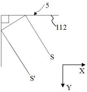
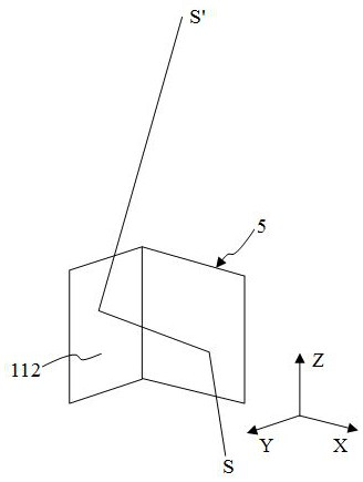
technical field [0001] The present application relates to the technical field of spatial stereo imaging, and in particular, to a preparation method of an optical imaging device with an array reflection unit. Background technique [0002] In the prior art, the stereoscopic imaging technology mainly uses two vertical mirrors to reflect the light twice according to the law of reflection, and the light is reflected twice by the two mutually perpendicular mirrors, so that the reflected light is re-converged in the air for imaging. The orthogonal mirror structure can reflect point light sources, line light sources or surface light sources, and the reflected light is still a point light source, line light source, and surface light source after the reflected light converges in the air. This special light path reflection effect makes aerial imaging technology practical. . However, at present, the aerial imaging effect of the optical imaging element using the orthogonal mirror surfac...

Claims


Application Information

Patent Timeline
Patent Type & Authority Patents(China)
IPC IPC(8): G02B30/35
CPCG02B30/35
Inventor 刘楠莫家豪
Owner 中显全息(北京)科技有限公司
Learn More