Detector supporting structure

A supporting structure and detector technology, which is applied in the direction of instruments, supporting machines, machine tables/supports, etc., can solve the problems of difficult elimination of stray light and difficulty of dust prevention on the focal plane, so as to improve the effect of dust prevention, improve the quality of imaging, reduce the The effect of stray light

Pending Publication Date: 2022-05-13
BEIJING RES INST OF SPATIAL MECHANICAL & ELECTRICAL TECH
View PDF0 Cites 0 Cited by
  • Summary
  • Abstract
  • Description
  • Claims
  • Application Information

AI Technical Summary

Problems solved by technology

The invention improves the rigidity of the support structure of the aerospace optical remote sensing camera detector, reduces the influence of stray light on the detector, and has an excellent dustproof effect, solves the problems of difficult dust prevention inside the focal plane and difficult elimination of stray light, and is an important tool for aerospace The development of optical remote sensing camera detectors provides technical support

Method used


Image

  • Detector supporting structure
  • Detector supporting structure
  • Detector supporting structure

Examples


Embodiment Construction

[0034] The following describes the present invention in detail, and the features and advantages of the present invention will become more clear and definite along with these descriptions.

[0035] The word "exemplary" is used exclusively herein to mean "serving as an example, embodiment, or illustration." Any embodiment described herein as "exemplary" is not necessarily to be construed as superior or better than other embodiments. While various aspects of the embodiments are shown in drawings, the drawings are not necessarily drawn to scale unless specifically indicated.

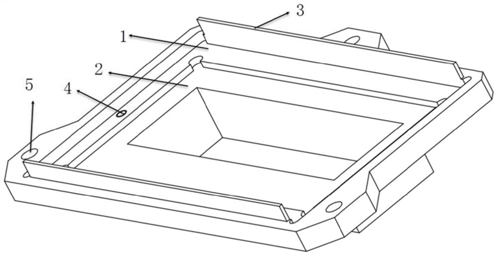
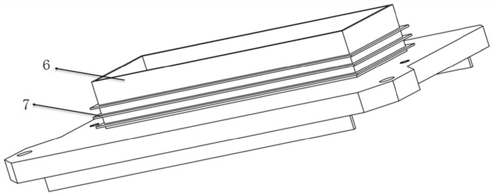
[0036] Such as figure 1 and figure 2 , the present invention is an integrated dust-proof, stray light-proof, high-rigidity detector support structure 9, including a support frame main body 1, ribs 3, aperture 6 and dust-proof fins 7;

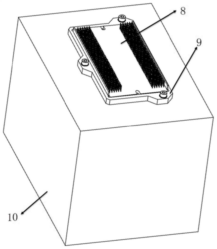
[0037] Such as image 3 and Figure 4 , the support frame main body 1 is provided with an opening as a light entrance, and the aerospace optical remote sensing camera de...


PUM


Abstract

The invention discloses a detector supporting structure which is used for supporting a spaceflight optical remote sensing camera detector. The detector supporting structure mainly comprises a supporting frame body, reinforcing ribs, a diaphragm and dustproof fins, the supporting frame body is provided with an opening serving as a light inlet, the aerospace optical remote sensing camera detector is fixedly installed on the upper surface of the supporting frame body, and the reinforcing ribs are arranged on the upper surface of the supporting frame body and located on the outer side of pins of the aerospace optical remote sensing camera detector; the lower surface of the supporting frame body is provided with a diaphragm protruding downwards, the diaphragm is located on the periphery of the light inlet, dustproof fins are arranged on the outer side of the diaphragm, the diaphragm extends into the focal plane frame, and after entering the focal plane frame, external light rays sequentially pass through the diaphragm and the light inlet to reach a spaceflight optical remote sensing camera detector. According to the invention, the rigidity of the spaceflight optical remote sensing camera detector supporting structure is improved, the influence of stray light on the detector is reduced, and the dustproof effect is excellent.

Description

technical field [0001] The invention belongs to the technical field of aerospace optics remote sensing camera detectors, and in particular relates to a support structure that can be used for space high-resolution camera detectors. Background technique [0002] Space optical remote sensing camera detectors usually use the detector support structure as the detector support structure, and connect with the focal plane frame through the detector support structure. The installation accuracy of the detector on the focal plane frame requires 1um~1.5um The stiffness of the structure is critical. Aerospace optical remote sensing cameras have higher and higher requirements for stray light, and the design of stray light inside the focal plane is an urgent problem to be solved. The pixel size of most detectors is less than 10um, which requires extremely high cleanliness. When the detector is imaging, the redundant objects exceeding the pixel size will seriously affect the imaging qualit...

Claims


Application Information

Patent Timeline
Patent Type & Authority Applications(China)
IPC IPC(8): G03B17/56G03B11/04B08B17/02F16M11/04
CPCG03B17/56G03B17/561G03B11/04B08B17/02F16M11/04
Inventor 李富强蔡伟军褚备王媛媛王静怡邱军晖史姣红罗廷云张荣辉范俊杰李思慧窦莲英丁世涛高扬邹宝成姜彦辉魏学敏
Owner BEIJING RES INST OF SPATIAL MECHANICAL & ELECTRICAL TECH
Why Eureka
Try Eureka